INSTALLATION PROCEDURE 1. INSTALL AIR CONDITIONING CONTROL ASSEMBLY (HAZARD WARNING SWITCH) 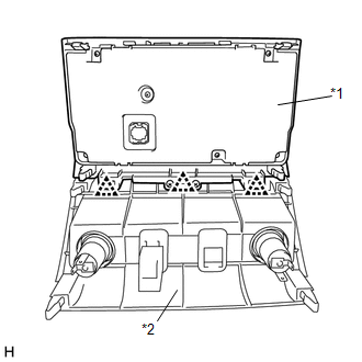
(a) Attach the 3 clips to connect the air conditioning control assembly (hazard warning switch) and center lower instrument panel finish panel. Text in Illustration
(b) Put protective tape around the air conditioning control assembly (hazard warning switch). (c) Connect each connector. (d) Attach the 8 clips, 2 claws and guide to install the air conditioning control assembly (hazard warning switch) with the center lower instrument panel finish panel. 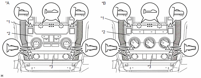 Text in Illustration Text in Illustration
2. INSTALL CENTER LOWER INSTRUMENT COVER (for Column Shift Type)
3. INSTALL FRONT CONSOLE BOX (for Floor Shift Type)
4. INSTALL REAR CONSOLE BOX ASSEMBLY (for Floor Shift Type)
5. INSTALL CONSOLE BOX CARPET (for Floor Shift Type)
6. INSTALL REAR CONSOLE END PANEL SUB-ASSEMBLY (for Floor Shift Type)
7. INSTALL UPPER CONSOLE PANEL SUB-ASSEMBLY (for Floor Shift Type)
8. INSTALL UPPER REAR CONSOLE PANEL SUB-ASSEMBLY (for Floor Shift Type)
9. INSTALL SHIFT LEVER KNOB SUB-ASSEMBLY (for Floor Shift Type)
|
Toyota Tundra Owners Manual > Steps to take in an
emergency: If you think something is
wrong
If you notice any of the following symptoms, your vehicle probably needs adjustment or repair. Contact your Toyota dealer as soon as possible. Visible symptoms Fluid leaks under the vehicle. (Water dripping from the air conditioning after use is normal.) Flat-looking tires or uneven tire wear Engin ...


