REMOVAL PROCEDURE 1. REMOVE SHIFT LEVER KNOB SUB-ASSEMBLY (for Floor Shift Type)
2. REMOVE UPPER REAR CONSOLE PANEL SUB-ASSEMBLY (for Floor Shift Type)
3. REMOVE UPPER CONSOLE PANEL SUB-ASSEMBLY (for Floor Shift Type)
4. REMOVE REAR CONSOLE END PANEL SUB-ASSEMBLY (for Floor Shift Type)
5. REMOVE CONSOLE BOX CARPET (for Floor Shift Type)
6. REMOVE REAR CONSOLE BOX ASSEMBLY (for Floor Shift Type)
7. REMOVE FRONT CONSOLE BOX (for Floor Shift Type)
8. REMOVE CENTER LOWER INSTRUMENT COVER (for Column Shift Type)
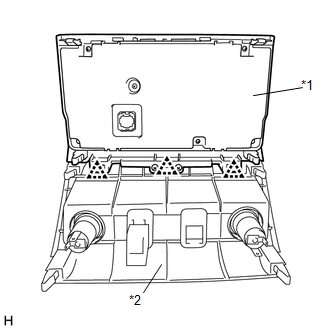
9. REMOVE AIR CONDITIONING CONTROL ASSEMBLY (HAZARD WARNING SWITCH) (a) Put protective tape around the air conditioning control assembly (hazard warning switch). (b) Using moulding remover B, detach the 8 clips, 2 claws and guide. (c) Disconnect each connector and remove the air conditioning control assembly (hazard warning switch) with the center lower instrument panel finish panel. 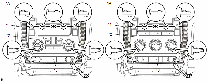 Text in Illustration Text in Illustration
|
Toyota Tundra Service Manual > Trailer Brake Control System: System Description
SYSTEM DESCRIPTION 1. FUNCTION DESCRIPTION *1 Trailer Brake Control Switch *2 GAIN (+/-) Selection Button *3 Manual Trailer Brake Output Slider *4 Steering Pad Switch Assembly (a) Steering Pad Switch Assembly: (1) The trailer brake type can be set by operating the steering pad switch assembly. (b) G ...