DESCRIPTION The outer mirror control ECU assembly controls the outer rear view mirror assembly (footwell lights). WIRING DIAGRAM 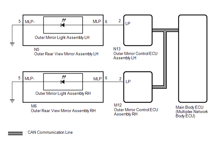
PROCEDURE
(a) Check the illumination of each footwell lights.
(a) Perform the Active Test according to the display on the Techstream. Click here
OK: Footwell light LH turn on.
(a) Remove the outer rear view mirror assembly LH. Click here (b) Inspect the outer rear view mirror assembly LH. Click here
(a) Disconnect the N5 outer rear view mirror assembly LH connector. (b) Disconnect the N13 outer mirror control ECU assembly LH connector. (c) Measure the resistance according to the value(s) in the table below. Standard Resistance:
(a) Temporarily replace the outer mirror light assembly LH with a new or normally functioning one. Click here (b) Perform the Active Test according to the display on the Techstream. Click here
OK: Footwell light LH turn on.
(a) Perform the Active Test according to the display on the Techstream. Click here
OK: Footwell light RH turn on.
(a) Remove the outer rear view mirror assembly RH. Click here (b) Inspect the outer rear view mirror assembly RH. Click here
(a) Disconnect the M6 outer rear view mirror assembly RH connector. (b) Disconnect the M12 outer mirror control ECU assembly RH connector. (c) Measure the resistance according to the value(s) in the table below. Standard Resistance:
(a) Temporarily replace the outer mirror light assembly RH with a new or normally functioning one. Click here (b) Perform the Active Test according to the display on the Techstream. Click here
OK: Footwell light RH turn on.
|
Toyota Tundra Service Manual > Audio And Visual System: Sound of Portable Player cannot be Heard from Speakers or Sound is Low
PROCEDURE 1. CHECK PORTABLE PLAYER SETTINGS (a) Check the portable player settings. (1) Check that the volume is not set to "0". (2) Check that mute is off. (b) Check that the sound of the portable player can be heard from the speakers. OK: Sound of the portable player can be heard from the speakers ...


