DESCRIPTION
The main body ECU (multiplex network body ECU) controls the daytime running lights.
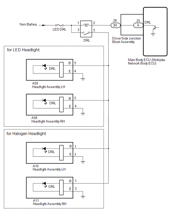
WIRING DIAGRAM
CAUTION / NOTICE / HINT
NOTICE:
Inspect the fuses for circuits related to this system before performing the following
procedure.
PROCEDURE
|
1.
|
PERFORM ACTIVE TEST USING TECHSTREAM
|
(a) Using the Techstream, perform the Active Test.
Click here 
Main Body
|
Tester Display
|
Test Part
|
Control Range
|
Diagnostic Note
|
|
Daytime Running Light
|
No. 1 daytime running relay (DRL)
|
OFF or ON
|
-
|
OK:
No. 1 daytime running relay (DRL) operates (daytime running lights turn on).
| OK |
 |
PROCEED TO NEXT SUSPECTED AREA SHOWN IN PROBLEM SYMPTOMS TABLE
|
| NG |

|
|
|
2.
|
INSPECT NO. 1 DAYTIME RUNNING LIGHT RELAY (DRL)
|
(a) Remove the No. 1 daytime running light relay (DRL) from the engine room relay
block and junction block.
(b) Inspect the No. 1 daytime running light relay (DRL).
Click here
| NG |
|
REPLACE NO. 1 DAYTIME RUNNING LIGHT RELAY (DRL)
|
| OK |
|
|
|
|
3.
|
CHECK HARNESS AND CONNECTOR (NO. 1 DAYTIME RUNNING LIGHT RELAY [DRL]
- BATTERY)
|
|
(a) Remove the No. 1 daytime running light relay (DRL) from the engine
room relay block and junction block.
|
|
|
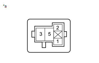
*a
|
Front view of wire harness connector
(to No. 1 Daytime Running Light Relay [DRL])
|
|
|
(b) Measure the voltage according to the value(s) in the table below.
Standard Voltage:
|
Tester Connection
|
Condition
|
Specified Condition
|
|
No. 1 daytime running light relay (DRL) terminal 1 - Body ground
|
Always
|
11 to 14 V
|
|
No. 1 daytime running light relay (DRL) terminal 3 - Body ground
|
Always
|
11 to 14 V
|
| NG |
|
REPAIR OR REPLACE HARNESS OR CONNECTOR
|
| OK |
|
|
|
|
4.
|
CHECK HARNESS AND CONNECTOR (NO. 1 DAYTIME RUNNING LIGHT RELAY [DRL]
- DRIVER SIDE JUNCTION BLOCK ASSEMBLY AND HEADLIGHT ASSEMBLY)
|
(a) Remove the No. 1 daytime running light relay (DRL) from the engine room relay
block and junction block.
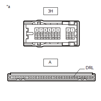
(b) Disconnect the 3H driver side junction block assembly connector.
(c) for LED Headlight:
(1) Disconnect the A59 headlight assembly LH connector.
(2) Disconnect the A58 headlight assembly RH connector.
(d) for Halogen Headlight:
(1) Disconnect the A10 headlight assembly LH connector.
(2) Disconnect the A11 headlight assembly RH connector.
(e) Measure the resistance according to the value(s) in the table below.
Standard Resistance:
for LED Headlight
|
Tester Connection
|
Condition
|
Specified Condition
|
|
No. 1 daytime running light relay (DRL) terminal 2 - 3H-28
|
Always
|
Below 1 Ω
|
|
No. 1 daytime running light relay (DRL) terminal 5 - A59-5 (B)
|
Always
|
Below 1 Ω
|
|
No. 1 daytime running light relay (DRL) terminal 2 or 3H-28 - Body ground
|
Always
|
10 kΩ or higher
|
|
No. 1 daytime running light relay (DRL) terminal 5 or A59-5 (B) - Body
ground
|
Always
|
10 kΩ or higher
|
for Halogen Headlight
|
Tester Connection
|
Condition
|
Specified Condition
|
|
No. 1 daytime running light relay (DRL) terminal 2 - 3H-28
|
Always
|
Below 1 Ω
|
|
No. 1 daytime running light relay (DRL) terminal 5 - A10-1 (B)
|
Always
|
Below 1 Ω
|
|
No. 1 daytime running light relay (DRL) terminal 2 or 3H-28 - Body ground
|
Always
|
10 kΩ or higher
|
|
No. 1 daytime running light relay (DRL) terminal 5 or A10-1 (B) - Body
ground
|
Always
|
10 kΩ or higher
|
| NG |
|
REPAIR OR REPLACE HARNESS OR CONNECTOR
|
| OK |
|
|
|
|
5.
|
CHECK DRIVER SIDE JUNCTION BLOCK ASSEMBLY
|
|
(a) Remove the driver side junction block assembly.
Click here
|
|
|
*a
|
Component without harness connected
(Driver Side Junction Block Assembly)
|
|
|
(b) Remove the main body ECU (multiplex network body ECU) from the driver side
junction block assembly.
Click here
(c) Measure the resistance according to the value(s) in the table below.
Standard Resistance:
|
Tester Connection
|
Condition
|
Specified Condition
|
|
3H-28 - A-25 (DRL)
|
Always
|
Below 1 Ω
|
| OK |
|
REPLACE MAIN BODY ECU (MULTIPLEX NETWORK BODY ECU)
|
| NG |
|
REPLACE DRIVER SIDE JUNCTION BLOCK ASSEMBLY
|
| 

