DESCRIPTION The main body ECU (multiplex network body ECU) receives headlight dimmer switch assembly (front fog light switch) information signals and illuminates the front fog lights. WIRING DIAGRAM 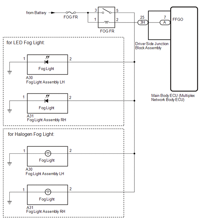
CAUTION / NOTICE / HINT NOTICE: Inspect the fuses for circuits related to this system before performing the following procedure. PROCEDURE
(a) Using the Techstream, perform the Active Test. Click here
OK: Front fog light relay (FOG FR) operates (front fog lights turn on).
(a) Remove the front fog light relay (FOG FR) from the engine room relay block and junction block. (b) Inscpect the front fog light relay (FOG FR). Click here
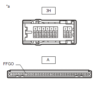
(a) Remove the front fog light relay (FOG FR) from the engine room relay block and junction block. (b) Disconnect the 3H driver side junction block assembly connector. (c) Disconnect the A30 fog light assembly LH connector. (d) Disconnect the A31 fog light assembly RH connector. (e) Measure the voltage according to the value(s) in the table below. Standard Voltage:
(f) Measure the resistance according to the value(s) in the table below. Standard Resistance:
(b) Remove the main body ECU (multiplex network body ECU) from the driver side junction block assembly. Click here (c) Measure the resistance according to the value(s) in the table below. Standard Resistance:
|
Toyota Tundra Service Manual > Touch Select 2-4 And High-low System: System Voltage (P0560)
DESCRIPTION This DTC is detected when the 4 wheel drive control ECU, which monitors the B terminal voltage, determines that the standard voltage is not met and detects a B terminal system malfunction. DTC Code DTC Detection Condition Diagnosis Condition Malfunction Status Malfunction Time Other Trou ...