DESCRIPTION The combination meter assembly receives the air conditioning control assembly (hazard warning signal switch) ON signal and controls the operation of the hazard warning lights. WIRING DIAGRAM 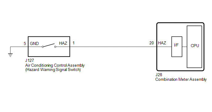
CAUTION / NOTICE / HINT NOTICE: When replacing the combination meter assembly, always replace it with a new one. If a combination meter assembly which was installed to another vehicle is used, the information stored in it will not match the information from the vehicle and a DTC may be stored. PROCEDURE
(a) Using the Techstream, read the Data List. Click here
OK: Normal condition listed above are displayed.
(a) Remove the air conditioning control assembly (hazard warning signal switch). Click here (b) Inspect the air conditioning control assembly (hazard warning signal switch). Click here
(a) Disconnect the J127 air conditioning control assembly (hazard warning signal switch) connector. (b) Disconnect the J28 combination meter assembly connector. (c) Measure the resistance according to the value(s) in the table below. Standard Resistance:
|
Toyota Tundra Service Manual > Navigation System: No Sound can be Heard from Speakers
CAUTION / NOTICE / HINT HINT: When the "iPhone" is connected to the USB port of the No. 1 stereo jack adapter, Entune audio may not be output. Before performing troubleshooting, disconnect the "iPhone" connected to the USB port of the No. 1 stereo jack adapter, change the audio output source of the ...


