DESCRIPTION The main body ECU (multiplex network body ECU) receives light control switch information signals and illuminates the low beam headlights. WIRING DIAGRAM 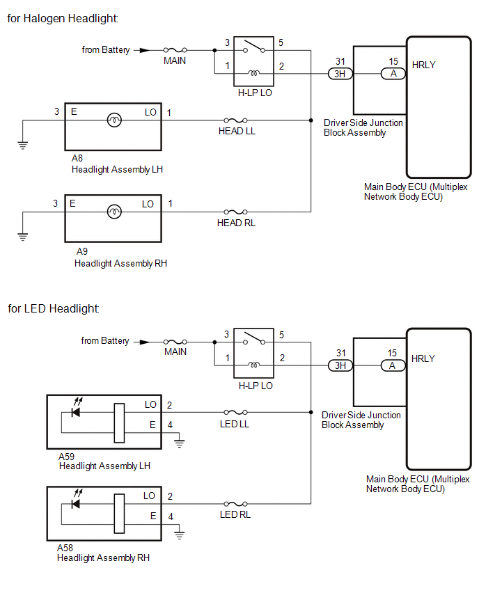
CAUTION / NOTICE / HINT NOTICE: Inspect the bulbs and fuses for circuits related to this system before performing the following procedure. PROCEDURE
(a) Using the Techstream, perform the Active Test. Click here
OK: Headlight relay (H-LP LO) operates (low beam headlights turn on).
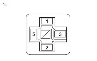
(a) Remove the headlight relay (H-LP LO) from the engine room relay block and junction block. (b) Inspect the headlight relay (H-LP LO). Click here
(b) Measure the voltage according to the value(s) in the table below. Standard Voltage:
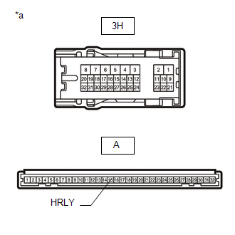
(a) Remove the headlight relay (H-LP LO) from the engine room relay block and junction block. (b) Disconnect the 3H driver side junction block assembly connector. (c) for Halogen Headlight: (1) Disconnect the A8 headlight assembly LH connector. (2) Disconnect the A9 headlight assembly RH connector. (d) for LED Headlight: (1) Disconnect the A59 headlight assembly LH connector. (2) Disconnect the A58 headlight assembly RH connector. (e) Measure the resistance according to the value(s) in the table below. Standard Resistance: for Halogen Headlight
(b) Remove the main body ECU (multiplex network body ECU) from the driver side junction block assembly. Click here (c) Measure the resistance according to the value(s) in the table below. Standard Resistance:
|
Toyota Tundra Service Manual > Steering Column Assembly(for Power Tilt And Power Telescopic Steering Column): Disassembly
DISASSEMBLY CAUTION / NOTICE / HINT NOTICE: When using a vise, do not overtighten it. PROCEDURE 1. REMOVE MULTIPLEX TILT AND TELESCOPIC ECU (a) Detach the claw to remove the multiplex tilt and telescopic ECU. 2. REMOVE TRANSPONDER KEY COIL (a) Using a screwdriver, widen the claws attached to the upp ...