DESCRIPTION
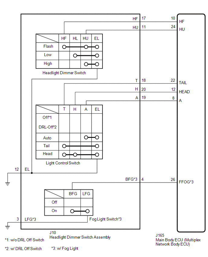
The main body ECU (multiplex network body ECU) receives the following signals:
- Light control switch in off*1, DRL-Off*2, tail, head or Auto position
- Headlight dimmer switch in high, low or high flash (pass) position
- Fog light switch front position*3
- *1: w/o DRL Off Switch
- *2: w/ DRL Off Switch
- *3: w/ Fog Light
WIRING DIAGRAM
PROCEDURE
|
1.
|
READ VALUE USING TECHSTREAM
|
(a) Using the Techstream, read the Data List.
Click here 
Main Body
|
Tester Display
|
Measurement Item / Range
|
Normal Condition
|
Diagnostic Note
|
|
Dimmer SW
|
Headlight dimmer switch High position signal / OFF or ON
|
OFF: Headlight dimmer switch not in High position
ON: Headlight dimmer switch in High position
|
-
|
|
Passing Light SW
|
Headlight dimmer switch Flash position signal / OFF or ON
|
OFF: Headlight dimmer switch not in Flash position
ON: Headlight dimmer switch in Flash position
|
-
|
|
Front Fog Light SW
|
Fog light switch front position signal
|
OFF: Fog light switch off
ON: Fog light switch in front position
|
w/ Fog Light
|
|
Auto Light SW
|
Light control switch Auto position signal
|
OFF: Light control switch not in Auto position
ON: Light control switch in Auto position
|
-
|
|
Head Light SW (Head)
|
Light control switch Head position signal
|
OFF: Light control switch not in Head position
ON: Light control switch in Head position
|
-
|
|
Head Light SW (Tail)
|
Light control switch Tail position signal
|
OFF: Light control switch not in Tail position
ON: Light control switch in Tail position
|
-
|
OK:
Normal condition listed above are displayed.
| OK |
 |
PROCEED TO NEXT SUSPECTED AREA SHOWN IN PROBLEM SYMPTOMS TABLE
|
| NG |

|
|
|
2.
|
INSPECT HEADLIGHT DIMMER SWITCH ASSEMBLY
|
(a) Remove the headlight dimmer switch assembly.
Click here
(b) Inspect the headlight dimmer switch assembly.
Click here
| NG |
|
REPLACE HEADLIGHT DIMMER SWITCH ASSEMBLY
|
| OK |
|
|
|
|
3.
|
CHECK HARNESS AND CONNECTOR (HEADLIGHT DIMMER SWITCH ASSEMBLY - MAIN
BODY ECU [MULTIPLEX NETWORK BODY ECU] AND BODY GROUND)
|
(a) Disconnect the J10 headlight dimmer switch assembly connector.
(b) Disconnect the J165 main body ECU (multiplex network body ECU) connector.
(c) Measure the resistance according to the value(s) in the table below.
Standard Resistance:
|
Tester Connection
|
Condition
|
Specified Condition
|
| *: w/ Fog Light |
|
J165-10 (HF) - J10-17 (HF)
|
Always
|
Below 1 Ω
|
|
J165-24 (HU) - J10-11 (HU)
|
Always
|
Below 1 Ω
|
|
J165-22 (TAIL) - J10-18 (T)
|
Always
|
Below 1 Ω
|
|
J165-12 (HEAD) - J10-20 (H)
|
Always
|
Below 1 Ω
|
|
J165-8 (A) - J10-19 (A)
|
Always
|
Below 1 Ω
|
|
J165-26 (FFOG) - J10-4 (BFG)*
|
Always
|
Below 1 Ω
|
|
J10-12 (EL) - Body ground
|
Always
|
Below 1 Ω
|
|
J10-3 (LFG) - Body ground*
|
Always
|
Below 1 Ω
|
|
J165-10 (HF) or J10-17 (HF) - Body ground
|
Always
|
10 kΩ or higher
|
|
J165-24 (HU) or J10-11 (HU) - Body ground
|
Always
|
10 kΩ or higher
|
|
J165-22 (TAIL) or J10-18 (T) - Body ground
|
Always
|
10 kΩ or higher
|
|
J165-12 (HEAD) or J10-20 (H) - Body ground
|
Always
|
10 kΩ or higher
|
|
J165-8 (A) or J10-19 (A) - Body ground
|
Always
|
10 kΩ or higher
|
|
J165-26 (FFOG) or J10-4 (BFG) - Body ground*
|
Always
|
10 kΩ or higher
|
| OK |
|
REPLACE MAIN BODY ECU (MULTIPLEX NETWORK BODY ECU)
|
| NG |
|
REPAIR OR REPLACE HARNESS OR CONNECTOR
|
| 

