DESCRIPTION
The combination meter assembly receives text data signals from the navigation receiver assembly*1 or radio and display receiver assembly*2 via local bus communication. Based on these signals, navigation system*1 or audio and visual system*2 information is displayed on the multi-information display. This DTC is stored when the combination meter assembly cannot receive the signal.
WIRING DIAGRAM w/ Navigation System: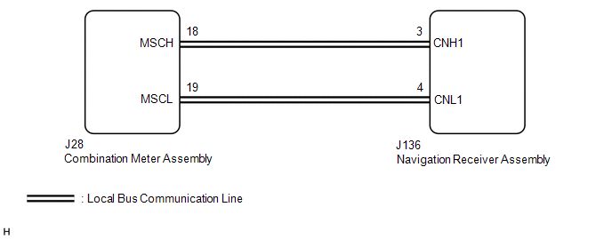 w/o Navigation
System: w/o Navigation
System: 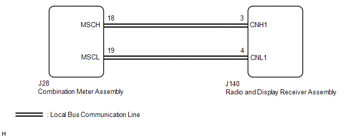
CAUTION / NOTICE / HINT HINT: DTC B150A may be stored if the battery voltage dropped. PROCEDURE
(a) w/ Navigation System: (1) Check if navigation system DTCs are output. Click here OK: Navigation system DTCs are not output. (b) w/o Navigation System: (1) Check if audio and visual system DTCs are output. Click here OK: Audio and visual system DTCs are not output.
(a) w/ Navigation System: (1) Disconnect the J136 navigation receiver assembly connector. (2) Disconnect the J28 combination meter assembly connector. (3) Measure the resistance according to the value(s) in the table below. Standard Resistance:
(b) w/o Navigation System: (1) Disconnect the J140 radio and display receiver assembly connector. (2) Disconnect the J28 combination meter assembly connector. (3) Measure the resistance according to the value(s) in the table below. Standard Resistance:
(a) Replace the combination meter assembly with a new one. Click here (b) Turn the ignition switch to ON and wait 30 seconds. NOTICE: A maximum of 30 seconds is required to send/receive the registration information between the combination meter assembly and navigation receiver assembly*! or radio and display receiver assembly*2.
(c) Operate the steering pad switch assembly and check that the audio tab illuminates. (d) Check for DTCs. Click here OK: The audio tab illuminates and DTC B150A is not output.
|
Toyota Tundra Service Manual > Power Door Lock Control System: Terminals Of Ecu
TERMINALS OF ECU 1. CHECK DRIVER SIDE JUNCTION BLOCK ASSEMBLY, MAIN BODY ECU (MULTIPLEX NETWORK BODY ECU) (a) Remove the main body ECU (multiplex network body ECU) from the driver side junction block assembly. Click here (b) Connect the driver side junction block assembly connectors. (c) Measure the ...


