DESCRIPTION The No. 2 ultrasonic sensor sends and receives ultrasonic waves. Based on the received wave, the sensor calculates the approximate distance value between the vehicle and the obstacle, and sends the distance value as a signal to the clearance warning ECU assembly. WIRING DIAGRAM 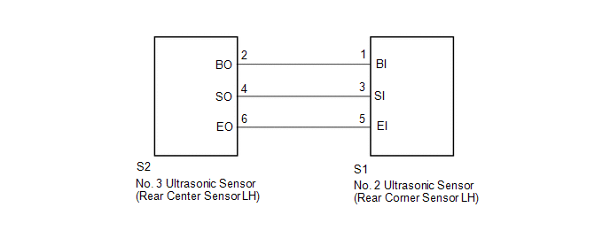 PROCEDURE
(a) Remove the No. 2 ultrasonic sensor (rear corner sensor LH) (See page
(b) Inspect the No. 2 ultrasonic sensor (rear corner sensor LH) (See page
(a) Disconnect the S1 No. 2 ultrasonic sensor (rear corner sensor LH) connector. (b) Disconnect the S2 No. 3 ultrasonic sensor (rear center sensor LH) connector. (c) Measure the resistance according to the value(s) in the table below. Standard Resistance:
|
Toyota Tundra Service Manual > Propeller Shaft Assembly(for 2wd): Removal
REMOVAL PROCEDURE 1. REMOVE PROPELLER WITH CENTER BEARING SHAFT ASSEMBLY (a) Place matchmarks on the propeller shaft flange and differential flange. Text in Illustration *a Matchmark (b) Remove the 4 bolts and 4 nuts. Then disconnect the propeller shaft from the differential side. (c) w/o Bearing Wa ...

 ).
).


