DESCRIPTION
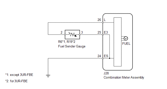
- The fuel sender gauge assembly has a variable resistance mechanism. The
resistance decreases when the fuel amount increases, and the resistance increases
when the fuel amount decreases. The fuel receiver gauge changes based on the
resistance of the fuel sender gauge assembly.
WIRING DIAGRAM
CAUTION / NOTICE / HINT
CAUTION:
Be careful of flames.
NOTICE:
When replacing the combination meter assembly, always replace it with a new one.
If a combination meter assembly which was installed to another vehicle is used,
the information stored in it will not match the information from the vehicle and
a DTC may be stored.
PROCEDURE
|
1.
|
PERFORM ACTIVE TEST USING TECHSTREAM (FUEL METER OPERATION)
|
(a) Using the Techstream, perform the Active Test.
Click here 
Combination Meter:
|
Tester Display
|
Test Part
|
Control Range
|
Diagnostic Note
|
|
Fuel Meter Operation
|
Fuel receiver gauge
|
OFF, Sender E, Empty, Warning, 1/4, 1/2, 3/4, Full or Sender F
|
Perform the test with the vehicle stopped and engine idling
|
OK:
Fuel receiver gauge indication is normal.
| NG |
 |
REPLACE COMBINATION METER ASSEMBLY
|
| OK |

|
|
|
2.
|
READ VALUE USING TECHSTREAM (FUEL INPUT)
|
(a) Using the Techstream, read the Data List.
Click here
Combination Meter:
|
Tester Display
|
Measurement Item/Range
|
Normal Condition
|
Diagnostic Note
|
|
Fuel Level
|
Fuel sender gauge input/Min.: 0, Max.: 127.5
|
Fuel sender input value
|
Unit: L
|
|
Result
|
Proceed to
|
|
Fuel level data displayed on the Techstream is almost the same as the
fuel receiver gauge indication.
|
A
|
|
Fuel level data displayed on the Techstream differs from the fuel receiver
gauge indication.
|
B
|
| B |
|
REPLACE COMBINATION METER ASSEMBLY
|
| A |
|
|
|
|
3.
|
CHECK HARNESS AND CONNECTOR (COMBINATION METER ASSEMBLY - FUEL SENDER
GAUGE ASSEMBLY)
|
- *1: except 3UR-FBE
- *2: for 3UR-FBE
(a) Disconnect the J28 combination meter assembly connector.
(b) Disconnect the R6*1 or R19*2 fuel sender gauge assembly connector.
(c) Measure the resistance according to the value(s) in the table below.
Standard Resistance:
except 3UR-FBE
|
Tester Connection
|
Condition
|
Specified Condition
|
|
J28-26 (L) - R6-2
|
Always
|
Below 1 Ω
|
|
J28-25 (E3) - R6-3
|
|
J28-24 (ES) - Body ground
|
|
J28-26 (L) or R6-2 - Body ground or other terminal
|
Always
|
10 kΩ or higher
|
|
J28-25 (E3) or R6-3 - Body ground or other terminal
|
for 3UR-FBE
|
Tester Connection
|
Condition
|
Specified Condition
|
|
J28-26 (L) - R19-2
|
Always
|
Below 1 Ω
|
|
J28-25 (E3) - R19-3
|
|
J28-24 (ES) - Body ground
|
|
J28-26 (L) or R19-2 - Body ground or other terminal
|
Always
|
10 kΩ or higher
|
|
J28-25 (E3) or R19-3 - Body ground or other terminal
|
| NG |
|
REPAIR OR REPLACE HARNESS OR CONNECTOR
|
| OK |
|
|
|
|
4.
|
INSPECT FUEL SENDER GAUGE ASSEMBLY
|
(a) Remove the fuel sender gauge assembly.
Click here
(b) Inspect the fuel sender gauge assembly.
Click here
| OK |
|
REPLACE COMBINATION METER ASSEMBLY
|
| NG |
|
REPLACE FUEL SENDER GAUGE ASSEMBLY
|
|



