DESCRIPTION This circuit is the power source circuit for the combination meter assembly. This circuit provides 2 power source types: one is a constant power source mainly used as a backup power source, and other is a power source mainly used for signal transmission. The constant power source is mainly used as a backup power source of the meter CPU. However, it is also used for communication. If a voltage of 12 V is not applied to terminal IG+ when the ignition switch ON, the indicator will not operate. WIRING DIAGRAM 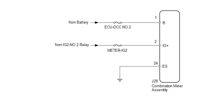
CAUTION / NOTICE / HINT NOTICE: Inspect the fuses for circuits related to this system before performing procedure. PROCEDURE
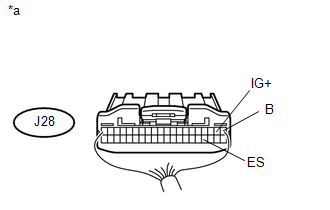
(a) Disconnect the J28 combination meter assembly connector. (b) Measure the resistance and voltage according to the value(s) in the table below. Standard Resistance:
Standard Voltage:
|
Toyota Tundra Service Manual > Power Window Control System(w/ Jam Protection Function): Operation Check
OPERATION CHECK 1. CHECK WINDOW LOCK SWITCH (a) Check that the front passenger side power window and rear power windows cannot be operated when the window lock switch of the master switch is pressed. OK: Operation of front passenger side power window and rear power windows is disabled. (b) Check tha ...


