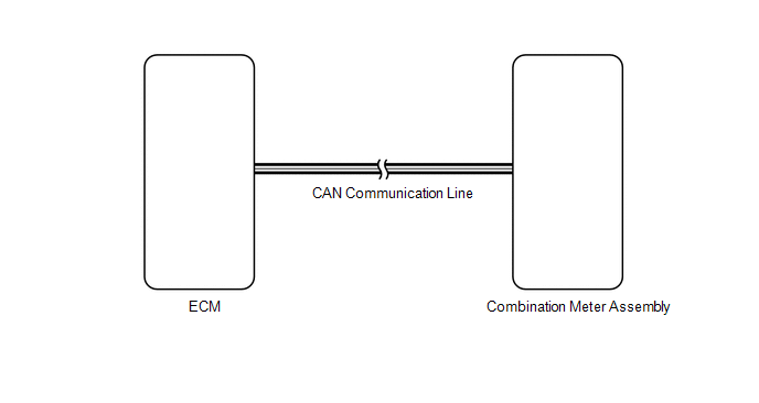
DESCRIPTION
The combination meter assembly receives engine speed signals from the ECM via
the CAN line. The combination meter assembly displays engine speed data that is
calculated based on the data received from the ECM.
WIRING DIAGRAM
PROCEDURE
|
1.
|
CHECK CAN COMMUNICATION SYSTEM
|
(a) Check if a CAN communication system DTC is output (See page
 ). ).
Result
|
Result
|
Proceed to
|
|
CAN communication system DTC is not output
|
A
|
|
CAN communication system DTC is output
|
B
|
| B |
 |
GO TO CAN COMMUNICATION SYSTEM
|
| A |

|
|
|
2.
|
PERFORM ACTIVE TEST USING TECHSTREAM (TACHOMETER)
|
(a) Operate the Techstream according to the display and select "Active Test"
(See page ).
Combination Meter:
|
Tester Display
|
Test Part
|
Control Range
|
Diagnostic Note
|
|
Tachometer Operation
|
Tachometer
|
0, 1000, 2000, 3000, 4000, 5000, 6000, 7000
|
Perform the test with the vehicle stopped and engine idling
|
OK:
Needle indication is normal.
HINT:
Confirm that the vehicle is stopped and engine idling.
| NG |
|
REPLACE COMBINATION METER ASSEMBLY
|
| OK |
|
|
|
|
3.
|
READ VALUE USING TECHSTREAM (TACHOMETER)
|
(a) Operate the Techstream according to the display and select "Data List" (See
page ).
Combination Meter:
|
Tester Display
|
Measurement Item/Range
|
Normal Condition
|
Diagnostic Note
|
|
Engine Rpm
|
Engine speed/Min.: 0, Max.: 12750
|
Idling: 650 to 750
|
Unit: rpm
|
OK:
Engine speed displayed on Techstream is almost the same as actual engine speed.
| OK |
|
REPLACE COMBINATION METER ASSEMBLY
|
| NG |
|
|
|
|
4.
|
READ VALUE USING TECHSTREAM (ENGINE SPEED)
|
(a) Operate the Techstream according to the display and select "Data List" (See
page ).
Engine:
|
Tester Display
|
Measurement Item/Range
|
Normal Condition
|
Diagnostic Note
|
|
Engine Speed
|
Engine speed/Min.: 0, Max.: 16838
|
Idling: 650 to 750
|
Unit: rpm
|
OK:
Engine speed displayed on Techstream is almost the same as actual engine speed.
Result
|
Result
|
Proceed to
|
|
OK
|
A
|
|
NG (for 1UR-FE)
|
B
|
|
NG (for 3UR-FE)
|
C
|
|
NG (for 3UR-FBE)
|
D
|
| A |
|
REPLACE COMBINATION METER ASSEMBLY
|
| B |
|
GO TO PROBLEM SYMPTOMS TABLE
|
| C |
|
GO TO PROBLEM SYMPTOMS TABLE
|
| D |
|
GO TO PROBLEM SYMPTOMS TABLE
|
| 

