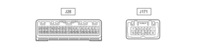
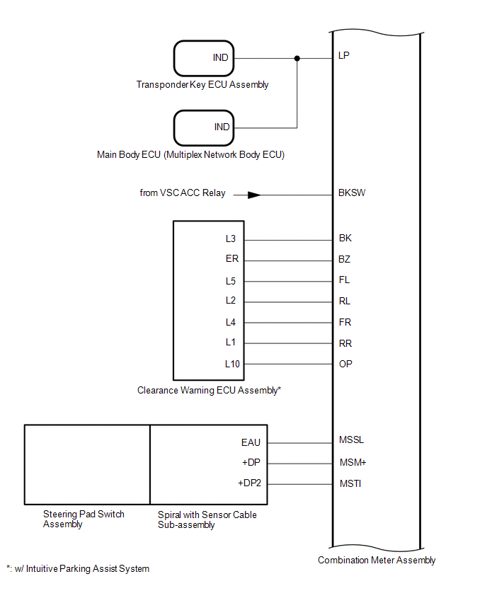
1. CHECK COMBINATION METER
(a) Measure the voltage, resistance and waveform according to the value(s) in
the table below.
|
Terminal No. (Symbol)
|
Wiring Color
|
Terminal Description
|
Condition
|
Specified Condition
|
| *1: w/ Intuitive Parking Assist System
*2: w/ Towing Package
*3: The minimum voltage value varies depending on the +BS terminal voltage
value. The minimum voltage is 85% or more of the +BS terminal voltage.
|
|
J28-1 (B) - Body ground
|
LG- Body ground
|
Power source
|
Always
|
11 to 14 V
|
|
J28-2 (IG+) - Body ground
|
B - Body ground
|
Ignitoin switch signal
|
Ignition switch off
|
Below 1 V
|
|
Ignition switch ON
|
11 to 14 V
|
|
J28-3 (BZ) - Body ground*1
|
V - Body ground
|
Clearance warning buzzer
|
Clearance warning buzzer sounding (when the back sonar senses something)
|
Pulse generation
|
|
J28-4 (BK) - Body ground*1
|
SB - Body ground
|
Ultrasonic sensor (for rear corner LH and RH)
|
Clearance warning indicator LED for back right and left illuminates
|
Below 3 V
|
|
J28-5 (OP) - Body ground*1
|
R - Body ground
|
Clearance warning ECU signal
|
Clearance warning indicator's operation indicator illuminates
|
Below 3 V
|
|
J28-6 (FR) - Body ground*1
|
W - Body ground
|
Ultrasonic sensor (for front corner RH)
|
Clearance warning indicator LED for front corner RH illuminates
|
Below 3 V
|
|
J28-7 (FL) - Body ground*1
|
LG - Body ground
|
Ultrasonic sensor (for front corner LH)
|
Clearance warning indicator LED for front corner LH illuminates
|
Below 3 V
|
|
J28-8 (RR) - Body ground*1
|
G - Body ground
|
Ultrasonic sensor (for rear corner RH)
|
Clearance warning indicator LED for rear corner RH illuminates
|
Below 3 V
|
|
J28-9 (RL) - Body ground*1
|
GR - Body ground
|
Ultrasonic sensor (for rear corner LH)
|
Clearance warning indicator LED for rear corner LH illuminates
|
Below 3 V
|
|
J28-10 (MSM+) - Body ground
|
P - Body ground
|
Steering pad switch signal
|
Ignition switch ON, enter, top and back switches on steering pad switch
not pushed
|
4.3 to 5.2 V
|
|
Ignition switch ON, enter switch on steering pad switch pushed
|
Below 0.6 V
|
|
Ignition switch ON, top switch on steering pad switch pushed
|
1.0 to 2.2 V
|
|
Ignition switch ON, back switch on steering pad switch pushed
|
2.3 to 3.4 V
|
|
J28-11 (MSTI) - Body ground
|
L - Body ground
|
Steering pad switch signal
|
Ignition switch ON, up, wn, right and left switches on steering pad switch
assembly not pushed
|
4.3 to 5.2 V
|
|
Ignition switch ON, left switch on steering pad switch pushed
|
Below 0.6 V
|
|
Ignition switch ON, up switch on steering pad switch pushed
|
1.0 to 2.2 V
|
|
Ignition switch ON, down switch on steering pad switch pushed
|
2.3 to 3.4 V
|
|
Ignition switch ON, right switch on steering pad switch pushed
|
3.4 to 4.5 V
|
|
J28-12 (MSSL) - Body ground
|
BE - Body ground
|
Ground
|
Always
|
Below 1 Ω
|
|
J28-13 (CHG-) - Body ground
|
B - Body ground
|
CHARGE warning light
|
Ignition switch ON, washer level warning light ON
|
Below 1 V
|
|
Ignition switch ON, washer level warning light OFF
|
11 to 14 V
|
|
J28-14 (SW) - Body ground
|
R - Body ground
|
Brake fluid level warning light signal
|
Ignition switch ON, BRAKE warning light ON
|
Below 1 V
|
|
Ignition switch ON, BRAKE warning light OFF
|
11 to 14 V
|
|
J28-15 (WLVL) - Body ground
|
SB - Body ground
|
Washer level warning light
|
Ignition switch ON, washer level warning light ON
|
Below 1 V
|
|
Ignition switch ON, washer level warning light OFF
|
11 to 14 V
|
|
J28-28 (EL) - Body ground
|
LG - Body ground
|
Turn signal L
|
Ignition switch ON, turn signal switch neutral position
|
Below 1 V
|
|
Ignition switch ON, turn signal switch turned to left
|
Alternating between below 1V and 11 to 14 V
|
|
J28-17 (ER) - Body ground
|
G - Body ground
|
Turn signal R
|
Ignition switch ON, turn signal switch neutral position
|
Below 1 V
|
|
Ignition switch ON, turn signal switch turned to right
|
Alternating between below 1V and 11 to 14 V
|
|
J28-18 (MSCH)
|
Y
|
CAN commuinication
|
-
|
-
|
|
J28-19 (MSCL)
|
W
|
CAN commuinication
|
-
|
-
|
|
J28-20 (HAZ) - Body ground
|
L - Body ground
|
Hazard warning signal switch signal (Output)
|
Hazard warning signal switch off
|
Below 1 V
|
|
Hazard warning signal switch on
|
Alternating between below 1V and 11 to 14 V
|
|
J28-22 (ILL-) - Body ground
|
BE - Body ground
|
Illumination signal
|
Headlight dimmer switch off
|
Below 1 V
|
|
Headlight dimmer switch in tail or head position
|
11 to 14 V
|
|
J28-23 (EP) - Body ground
|
W-B - Body ground
|
Illumination ground
|
Always
|
Below 1 Ω
|
|
J28-24 (ES) - Body ground
|
BR - Body ground
|
Ground
|
Always
|
Below 1 Ω
|
|
J28-25 (E3) - Body ground
|
Y - Body ground
|
Fuel sender gauge ground
|
Always
|
Below 1 Ω
|
|
J28-26 (L) - Body ground
|
V - Body ground
|
Fuel sender gauge
|
Ignition switch ON, fuel sender gauge ON
|
Below 1 V
|
|
Ignition switch ON, fuel sender gauge OFF
|
11 to 14 V
|
|
J28-27 (S) - Body ground
|
L - Body ground
|
Oil pressure warning light
|
Ignition switch ON, oil pressure warning light ON
|
Below 1 V
|
|
Ignition switch ON, oil pressure warning light OFF
|
11 to 14 V
|
|
J28-28 (SW) - Body ground
|
BE - Body ground
|
Turn signal switch signal
|
Ignition switch ON, LH and RH turn signal switch off
|
11 to 14 V
|
|
Ignition switch ON, LH or RH turn signal switch on
|
Below 1 V
|
|
J28-29 (+S) - Body ground
|
SB - Body ground
|
Speed signal (output)
|
Ignition switch ON, wheel turned slowly
|
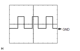
Pulse generation
(See waveform 1)
|
|
J28-30 (SI) - Body ground
|
LG - Body ground
|
Speed signal for other system (Input)
|
Ignition switch ON, wheel being rotated
|
Pulse generation
(See waveform 1)
|
|
J28-31 (P) - Body ground
|
V - Body ground
|
A/T shift position signal P
|
Ignition switch ON, shift lever not in P
|
Below 1 V
|
|
Ignition switch ON, shift lever in P
|
11 to 14 V
|
|
J28-32 (R) - Body ground
|
R - Body ground
|
A/T shift position signal R
|
Ignition switch ON, shift lever not in R
|
Below 1 V
|
|
Ignition switch ON, shift lever in R
|
11 to 14 V
|
|
J28-33 (N) - Body ground
|
W - Body ground
|
A/T shift position signal N
|
Ignition switch ON, shift lever not in N
|
Below 1 V
|
|
Ignition switch ON, shift lever in N
|
11 to 14 V
|
|
J28-34 (D) - Body ground
|
L - Body ground
|
A/T shift position signal D
|
Ignition switch ON, shift lever not in D
|
Below 1 V
|
|
Ignition switch ON, shift lever in D
|
11 to 14 V
|
|
J28-35 (4) - Body ground
|
V - Body ground
|
A/T shift position signal S
|
Ignition switch ON, shift lever not in S
|
Below 1 V
|
|
Ignition switch ON, shift lever in S
|
11 to 14 V
|
|
J28-36 (LP) - Body ground
|
BE - Body ground
|
Security indicator light signal
|
Immobiliser set status (SET)
|
Alternating between 11 to 14 V and below 1 V
|
|
Immobiliser set status (UNSET)
|
Below 1 V
|
|
J28-38 (BKSW) - Body ground
|
R - Body ground
|
Stop light control relay (stop light switch assembly) input
|
Stop light switch assembly on → off (Brake pedal depressed → released)
|
(+BS x 0.85) to 14 V*3 → Below 1.5 V
|
|
J28-39 (CANH)
|
SB
|
CAN commuinication
|
-
|
-
|
|
J28-40 (CANL)
|
W
|
CAN commuinication
|
-
|
-
|
|
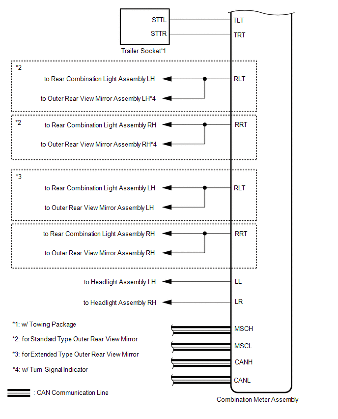
J171-1 (TRT) - Body ground*2
|
B - Body ground
|
Trailer socket signal RH signal
|
Ignition switch ON, turn signal switch neutral position
|
Below 1 V
|
|
Ignition switch ON, turn signal switch turned to right
|
Alternating between below 1V and 11 to 14 V
|
|
J171-7 (TLT) - Body ground*2
|
Y - Body ground
|
Trailer socket signal LH signal
|
Ignition switch ON, turn signal switch neutral position
|
Below 1 V
|
|
Ignition switch ON, turn signal switch turned to left
|
Alternating between below 1V and 11 to 14 V
|
|
J171-8 (B) - Body ground
|
V - Body ground
|
Power source
|
Always
|
11 to 14 V
|
|
J171-9 (LL) - Body ground
|
G - Body ground
|
Turn signal L
|
Ignition switch ON, turn signal switch neutral position
|
Below 1 V
|
|
Ignition switch ON, turn signal switch turned to left
|
Alternating between below 1V and 11 to 14 V
|
|
J171-10 (LR) - Body ground
|
BE - Body ground
|
Turn signal R
|
Ignition switch ON, turn signal switch neutral position
|
Below 1 V
|
|
Ignition switch ON, turn signal switch turned to right
|
Alternating between below 1V and 11 to 14 V
|
|
J171-11 (RLT) - Body ground
|
B - Body ground
|
Rear turn signal light LH signal
|
Ignition switch ON, turn signal switch neutral position
|
Below 1 V
|
|
Ignition switch ON, turn signal switch turned to left
|
Alternating between below 1V and 11 to 14 V
|
|
J171-12 (RRT) - Body ground
|
SB - Body ground
|
Rear turn signal light RH signal
|
Ignition switch ON, turn signal switch neutral position
|
Below 1 V
|
|
Ignition switch ON, turn signal switch turned to right
|
Alternating between below 1V and 11 to 14 V
|
|
J171-13 (B) - Body ground
|
GR - Body ground
|
Power source
|
Always
|
11 to 14 V
|
When the system is functioning normally, one wheel revolution generates 4 pulses.
As the vehicle speed increases, the width indicated by (A) in the illustration narrows.
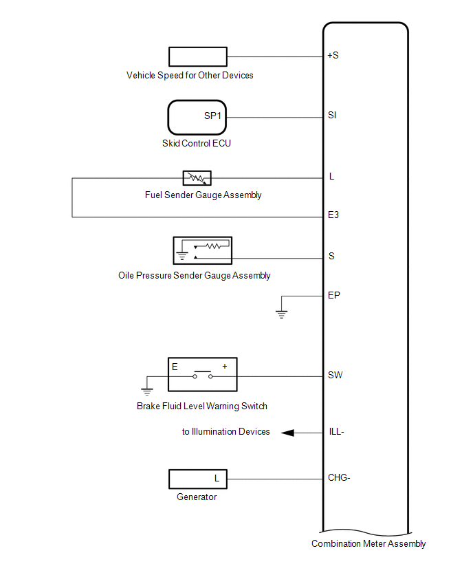
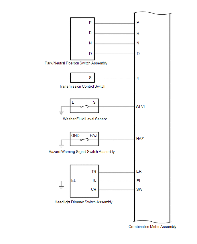
2. CHECK COMBINATION METER INNER CIRCUIT