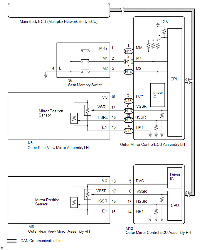
DESCRIPTION
When the seat memory switch is operated, the switch input signal is sent via
CAN communication from the outer mirror control ECU assembly LH to the main body
ECU (multiplex network body ECU). The main body ECU (multiplex network body ECU)
then sends the memorization request or recall request signals to the outer mirror
control ECU assembly LH and outer mirror control ECU assembly RH via CAN communication.
The outer mirror control ECU assembly LH and outer mirror control ECU assembly RH
memorize the mirror position when a memorization request signal is received, and
move the mirror to the memorized position when a recall request signal is received.
WIRING DIAGRAM
CAUTION / NOTICE / HINT
NOTICE:
First perform the communication function inspections in How to Proceed with Troubleshooting
to confirm that there are no CAN communication malfunctions before troubleshooting
this problem.
Click here 
PROCEDURE
|
1.
|
CHECK OUTER REAR VIEW MIRROR ASSEMBLY FUNCTION
|
(a) Check that the mirror operates.
Click here
OK:
Mirror operates normally.
|
Result
|
Proceed to
|
|
OK
|
A
|
|
NG (Driver side outer rear view mirror assembly does not operate)
|
B
|
|
NG (Front passenger side outer rear view mirror assembly does not operate)
|
C
|
| B |
 |
GO TO OTHER FLOWCHART (Power Mirror cannot be Adjusted with Power Mirror
Switch)
|
| C |
|
GO TO OTHER FLOWCHART (Power Mirror cannot be Adjusted with Power Mirror
Switch)
|
| A |

|
|
|
2.
|
CHECK SEAT MEMORY SWITCH (SEAT POSITION MEMORY FUNCTION)
|
(a) Perform a seat memory operation properly.
Click here
(b) When any seat memory switch (M1 or M2 switch) is pressed, check that the
driver side seat moves to the memorized position.
OK:
Driver side seat moves to memorized position.
| NG |
|
GO TO FRONT POWER SEAT CONTROL SYSTEM
|
| OK |
|
|
|
|
3.
|
READ VALUE USING TECHSTREAM (MIRROR MEMORY)
|
(a) Using the Techstream, read the Data List.
Click here
(1) for LH side:
Mirror L
|
Tester Display
|
Measurement Item/Range
|
Normal Condition
|
Diagnostic Note
|
|
Mirror Memory No.1
|
Mirror position memorized in memory switch M1 / OFF or ON
|
OFF: Not memorized
ON: Memorized
|
-
|
|
Mirror Memory No.2
|
Mirror position memorized in memory switch M2 / OFF or ON
|
OFF: Not memorized
ON: Memorized
|
-
|
(2) for RH side:
Mirror R
|
Tester Display
|
Measurement Item/Range
|
Normal Condition
|
Diagnostic Note
|
|
Mirror Memory No.1
|
Mirror position memorized in memory switch M1 / OFF or ON
|
OFF: Not memorized
ON: Memorized
|
-
|
|
Mirror Memory No.2
|
Mirror position memorized in memory switch M2 / OFF or ON
|
OFF: Not memorized
ON: Memorized
|
-
|
OK:
The display is as specified in the normal condition column.
|
Result
|
Proceed to
|
|
LH side mirror position cannot be memorized
|
A
|
|
LH side mirror position memory exists but cannot be recalled
|
B
|
|
RH side mirror position cannot be memorized
|
C
|
|
RH side mirror position memory exists but cannot be recalled
|
D
|
|
Both LH side mirror position and RH side mirror position cannot be memorized
|
E
|
| B |
|
REPLACE OUTER MIRROR CONTROL ECU ASSEMBLY LH
|
| C |
|
GO TO STEP 6
|
| D |
|
REPLACE OUTER MIRROR CONTROL ECU ASSEMBLY RH
|
| E |
|
REPLACE MAIN BODY ECU (MULTIPLEX NETWORK BODY ECU)
|
| A |
|
|
|
|
4.
|
CHECK HARNESS AND CONNECTOR (OUTER REAR VIEW MIRROR ASSEMBLY LH - OUTER
MIRROR CONTROL ECU ASSEMBLY LH)
|
(a) Disconnect the N5 outer rear view mirror assembly LH connector.
(b) Disconnect the N13 outer mirror control ECU assembly LH connector.
(c) Measure the resistance according to the value(s) in the table below.
Standard Resistance:
|
Tester Connection
|
Condition
|
Specified Condition
|
|
N5-18 (VC) - N13-5 (LVC)
|
Always
|
Below 1 Ω
|
|
N5-16 (HSRL) - N13-13 (HSSR)
|
Always
|
Below 1 Ω
|
|
N5-17 (VSRL) - N13-6 (VSSR)
|
Always
|
Below 1 Ω
|
|
N5-15 (E1) - N13-14 (LE1)
|
Always
|
Below 1 Ω
|
|
N5-18 (VC) or N13-5 (LVC) - Body ground
|
Always
|
10 kΩ or higher
|
|
N5-16 (HSRL) or N13-13 (HSSR) - Body ground
|
Always
|
10 kΩ or higher
|
|
N5-17 (VSRL) or N13-6 (VSSR) - Body ground
|
Always
|
10 kΩ or higher
|
|
N5-15 (E1) or N13-14 (LE1) - Body ground
|
Always
|
10 kΩ or higher
|
| NG |
|
REPAIR OR REPLACE HARNESS OR CONNECTOR
|
| OK |
|
|
|
|
5.
|
CHECK OUTER REAR VIEW MIRROR ASSEMBLY LH
|
(a) Temporarily replace the outer rear view mirror assembly LH with a new or
known good one.
Click here
(b) Check that the memory and reactivation function operates.
Click here
OK:
Memory and reactivation function operates normally.
| OK |
|
END (OUTER REAR VIEW MIRROR ASSEMBLY LH WAS DEFECTIVE)
|
| NG |
|
REPLACE OUTER MIRROR CONTROL ECU ASSEMBLY LH
|
|
6.
|
CHECK HARNESS AND CONNECTOR (OUTER REAR VIEW MIRROR ASSEMBLY RH - OUTER
MIRROR CONTROL ECU ASSEMBLY RH)
|
(a) Disconnect the M6 outer rear view mirror assembly RH connector.
(b) Disconnect the M12 outer mirror control ECU assembly RH connector.
(c) Measure the resistance according to the value(s) in the table below.
Standard Resistance:
|
Tester Connection
|
Condition
|
Specified Condition
|
|
M6-18 (VC) - M12-5 (RVC)
|
Always
|
Below 1 Ω
|
|
M6-16 (HSSR) - M12-13 (HSSR)
|
Always
|
Below 1 Ω
|
|
M6-17 (VSSR) - M12-6 (VSSR)
|
Always
|
Below 1 Ω
|
|
M6-15 (E1) - M12-14 (RE1)
|
Always
|
Below 1 Ω
|
|
M6-18 (VC) or M12-5 (RVC) - Body ground
|
Always
|
10 kΩ or higher
|
|
M6-16 (HSSR) or M12-13 (HSSR) - Body ground
|
Always
|
10 kΩ or higher
|
|
M6-17 (VSSR) or M12-6 (VSSR) - Body ground
|
Always
|
10 kΩ or higher
|
|
M6-15 (E1) or M12-14 (RE1) - Body ground
|
Always
|
10 kΩ or higher
|
| NG |
|
REPAIR OR REPLACE HARNESS OR CONNECTOR
|
| OK |
|
|
|
|
7.
|
CHECK OUTER REAR VIEW MIRROR ASSEMBLY RH
|
(a) Temporarily replace the outer rear view mirror assembly RH with a new or
known good one.
Click here
(b) Check that the memory and reactivation function operates.
Click here
OK:
Memory and reactivation function operates normally.
| OK |
|
END (OUTER REAR VIEW MIRROR ASSEMBLY RH WAS DEFECTIVE)
|
| NG |
|
REPLACE OUTER MIRROR CONTROL ECU ASSEMBLY RH
|
| 

