DESCRIPTION When the outer mirror switch assembly (mirror master switch) is operated, right/left selection signals are sent to the main body ECU (multiplex network body ECU). The main body ECU (multiplex network body ECU) sends the received right/left selection signals to the outer mirror control ECU assemblies via CAN communication. WIRING DIAGRAM 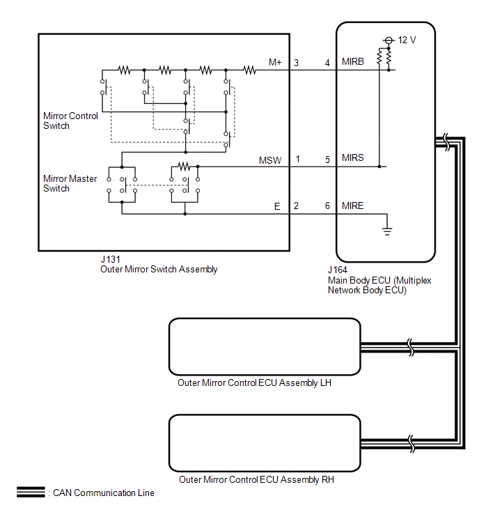
CAUTION / NOTICE / HINT NOTICE: First perform the communication function inspections in How to Proceed with Troubleshooting to confirm that there are no CAN communication malfunctions before troubleshooting this problem. Click here PROCEDURE
(a) Using the Techstream, read the Data List. Click here
OK: The display is as specified in the normal condition column.
(a) Remove the outer mirror switch assembly. Click here (b) Inspect the outer mirror switch assembly. Click here
(a) Disconnect the J131 outer mirror switch assembly connector. (b) Disconnect the J164 main body ECU (multiplex network body ECU) connector. (c) Measure the resistance according to the value(s) in the table below. Standard Resistance:
|
Toyota Tundra Service Manual > Can Communication System: ECM Communication Stop Mode
DESCRIPTION Detection Item Symptom Trouble Area ECM Communication Stop Mode Any of the following conditions are met: Communication stop for "ECM (Engine)" is indicated on the "Communication Bus Check" screen of the Techstream. Communication system DTCs (DTCs that start with U) that correspond to "EC ...


