Toyota Tundra Service Manual: System Diagram

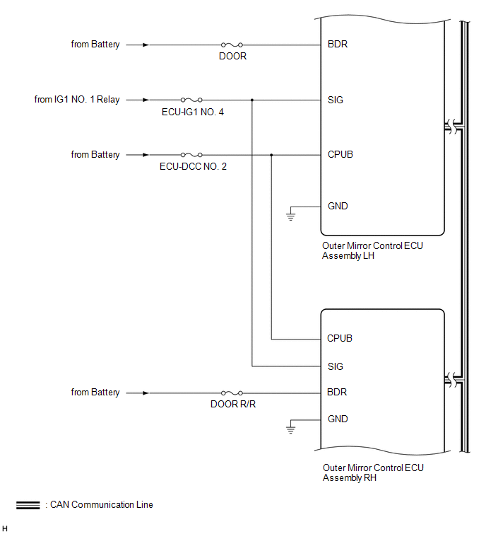
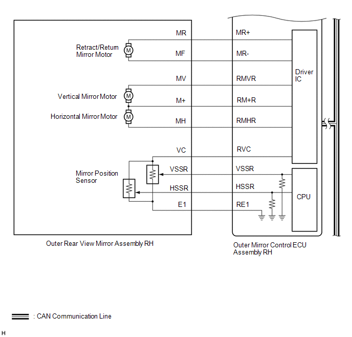
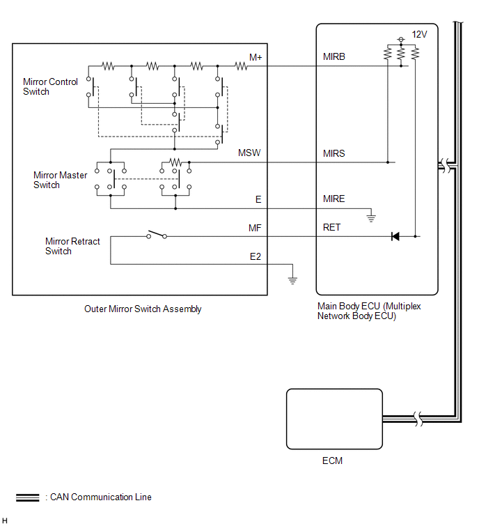
SYSTEM DIAGRAM

1. POWER MIRROR CONTROL SYSTEM
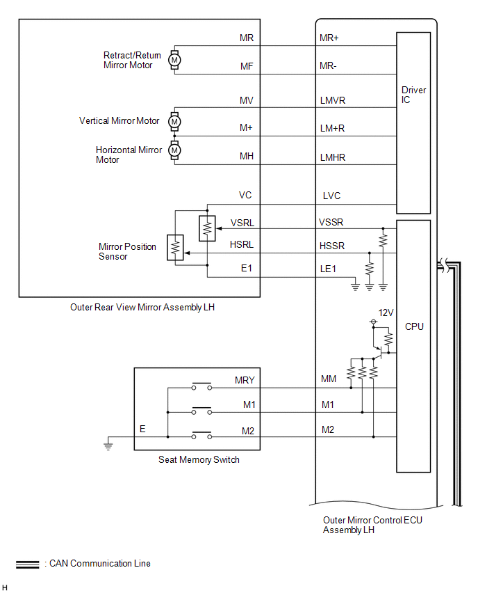
Communication Table

Sender

Receiver

Communication Signal

Communication Line

Main body ECU (multiplex network body ECU)

Outer mirror control ECU assembly

  • Mirror master switch signal
  • Mirror control switch signal
  • Mirror retract switch signal

CAN

ECM

Outer mirror control ECU assembly

Shift position R signal

CAN

Outer Mirror Control ECU Assembly LH

Front Power Seat Switch LH

  • Seat memory switch M1 signal
  • Seat memory switch M2 signal
  • Seat memory switch SET signal

CAN

2. EC MIRROR SYSTEM

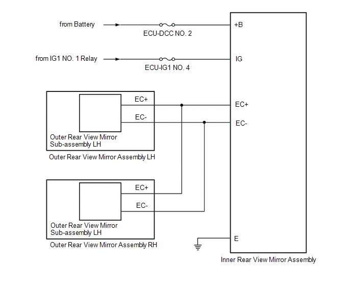
3. MIRROR HEATER SYSTEM
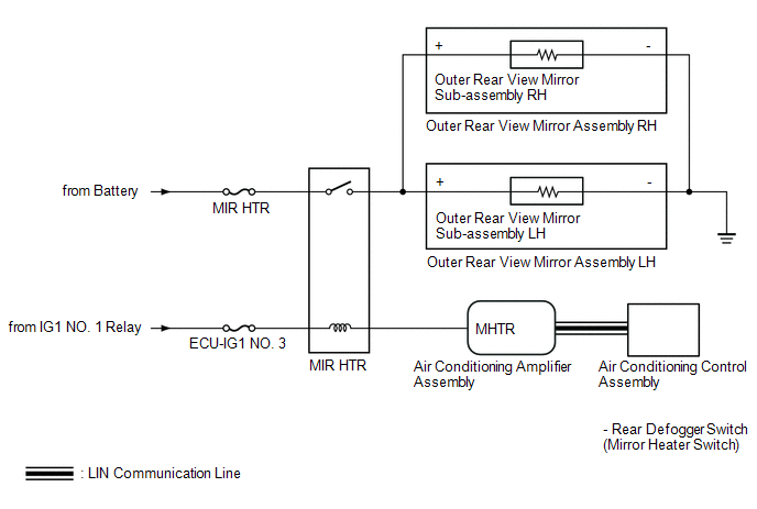
Communication Table

Sender

Receiver

Communication Signal

Communication Line

Air conditioning control assembly

Air conditioning amplifier assembly

Mirror heater switch signal

LIN

    System Description

    Terminals Of Ecu

    See More:

    Toyota Tundra Service Manual > Door Lock: Wireless Door Lock Buzzer
    Components COMPONENTS ILLUSTRATION *A for Type A *B for Type B *C for Type C - - *1 FRONT END PANEL LH *2 RADIATOR GRILLE SUB-ASSEMBLY *3 WIRELESS DOOR LOCK BUZZER - - Installation INSTALLATION PROCEDURE 1. INSTALL WIRELESS DOOR LOCK BUZZER (a) Attach the clamp to install the wireless door lock buzz ...

    Toyota Tundra Owners Manual

    Toyota Tundra Service Manual

    © 2026 Copyright www.ttundra.com
    0.0317