Toyota Tundra Service Manual: Removal

REMOVAL

PROCEDURE

1. REMOVE UPPER REAR CONSOLE PANEL SUB-ASSEMBLY

2. REMOVE UPPER CONSOLE PANEL SUB-ASSEMBLY

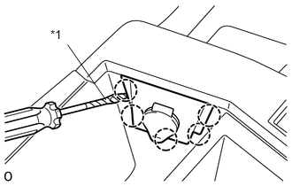
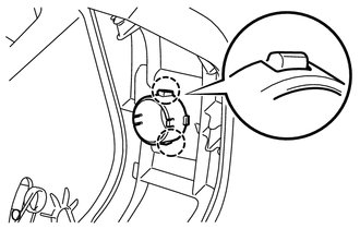
3. REMOVE CONSOLE BOX BEZEL

(a) Disconnect the connector.

(b) Using a screwdriver, detach the 5 claws and remove the console box bezel.

HINT:

Tape the screwdriver tip before use.

Text in Illustration

*1

Protective Tape

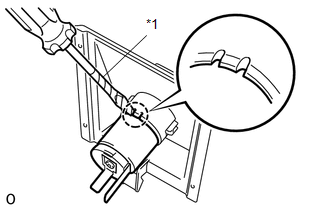
4. REMOVE POWER OUTLET SOCKET ASSEMBLY

(a) Using a screwdriver, detach the claw and remove the power outlet socket assembly.

HINT:

Tape the screwdriver tip before use.

Text in Illustration

*1

Protective Tape

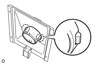
5. REMOVE POWER OUTLET SOCKET COVER

(a) Detach the 2 claws and remove the power outlet socket cover.

6. REMOVE REAR CONSOLE END PANEL SUB-ASSEMBLY (for Double Cab)

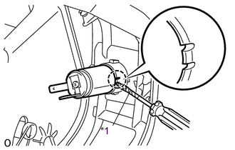
7. REMOVE POWER OUTLET SOCKET ASSEMBLY (for Double Cab)

(a) Using a screwdriver, detach the claw and remove the power outlet socket assembly.

HINT:

Tape the screwdriver tip before use.

Text in Illustration

*1

Protective Tape

8. REMOVE POWER OUTLET SOCKET COVER (for Double Cab)

(a) Detach the 2 claws and remove the power outlet socket cover.

    Installation

    Power Outlet Socket(for Crewmax Column Shift Type)

    See More:

    Toyota Tundra Service Manual > Navigation System: A/C ECU Vehicle Information Reading/Writing Processor Malfunction (B15F5)
    DESCRIPTION This DTC is stored when items controlled by the Air conditioning amplifier assembly cannot be customized via the navigation system vehicle customization screen. HINT: The Air conditioning amplifier assembly controls the air conditioning system related items that are customizable via the ...

    Toyota Tundra Owners Manual

    Toyota Tundra Service Manual

    © 2025 Copyright www.ttundra.com
    0.0295