DESCRIPTION This circuit supplies power to the millimeter wave radar sensor assembly when the ignition switch is ON. WIRING DIAGRAM 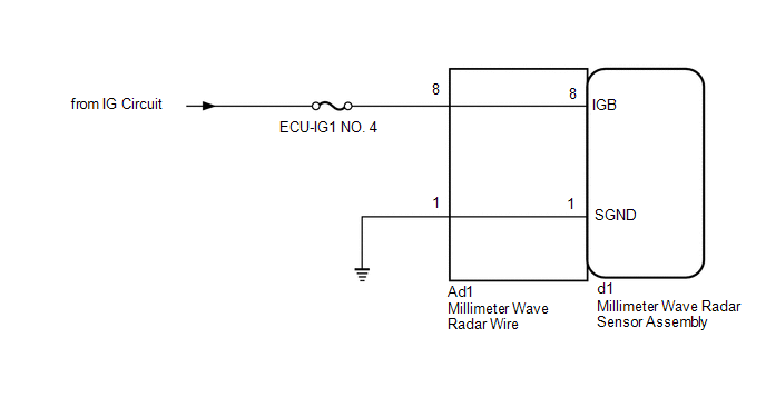
CAUTION / NOTICE / HINT NOTICE: Inspect the fuses for circuits related to this system before performing the following inspection procedure. PROCEDURE
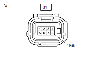
(b) Turn the ignition switch to ON. (c) Measure the voltage according to the value(s) in the table below. Standard Voltage:
(d) Turn the ignition switch off. (e) Connect the d1 millimeter wave radar sensor assembly connector.
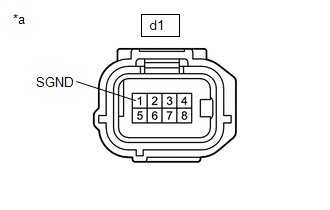
(b) Measure the resistance according to the value(s) in the table below. Standard Resistance:
(c) Connect the d1 millimeter wave radar sensor assembly connector.
(a) Disconnect the d1 millimeter wave radar sensor assembly connector. (b) Disconnect the Ad1 millimeter wave radar wire connector. (c) Measure the resistance according to the value(s) in the table below. Standard Resistance:
(d) Connect the d1 millimeter wave radar sensor assembly connector. (e) Connect the Ad1 millimeter wave radar wire connector.
(a) Disconnect the d1 millimeter wave radar sensor assembly connector. (b) Disconnect the Ad1 millimeter wave radar wire connector. (c) Measure the resistance according to the value(s) in the table below. Standard Resistance:
(d) Connect the d1 millimeter wave radar assembly connector. (e) Connect the Ad1 millimeter wave radar sensor wire connector.
|
Toyota Tundra Service Manual > Rear Bumper(for Resin Type Bumper): Installation
INSTALLATION CAUTION / NOTICE / HINT CAUTION: As the rear bumper cover is extremely heavy, the engine lifter may suddenly drop if the instructions listed in the repair manual are not followed. Therefore, always follow the instructions listed in the repair manual when performing this procedure. PROCE ...