PARTS LOCATION ILLUSTRATION 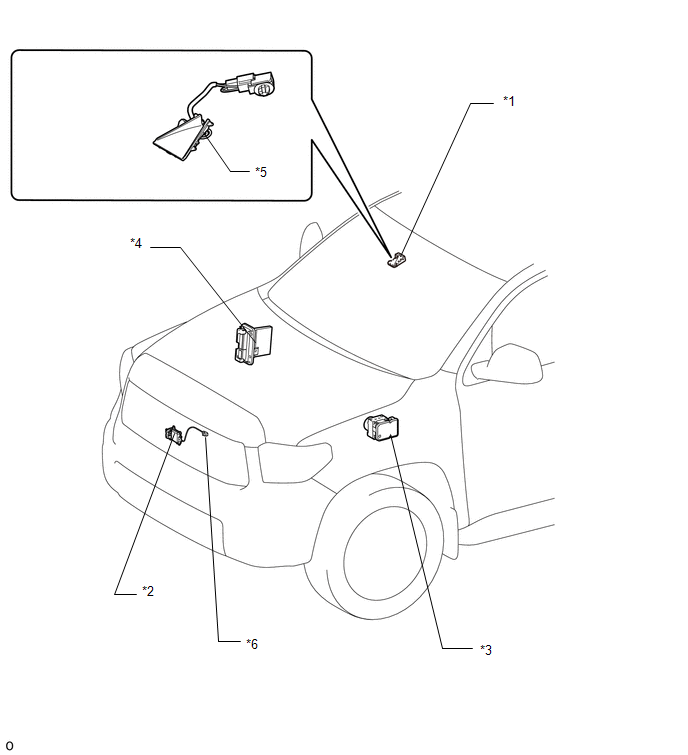
ILLUSTRATION 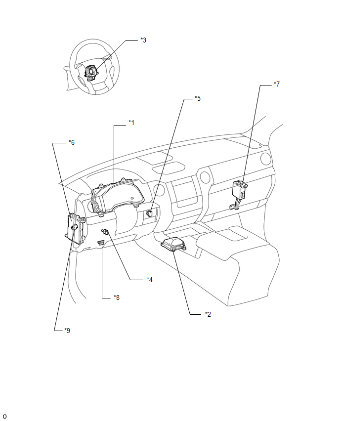
|
Toyota Tundra Owners Manual > For safe use: Exhaust gas precautions
Harmful substance to the human body is included in exhaust gases if inhale. WARNINGExhaust gases include harmful carbon monoxide (CO), which is colorless and odorless. Observe the following precautions. Failure to do so may cause exhaust gases to enter the vehicle and may lead to an accident ...


