Components COMPONENTS ILLUSTRATION 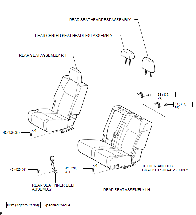
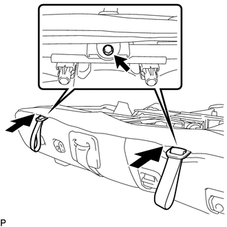
Installation INSTALLATION CAUTION / NOTICE / HINT CAUTION: Wear protective gloves. Sharp areas on the parts may injure your hands. PROCEDURE 1. INSTALL TETHER ANCHOR BRACKET SUB-ASSEMBLY
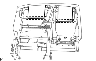
(b) Attach the 2 hooks of the separate type rear seatback cover. 2. INSTALL REAR CENTER SEAT HEADREST ASSEMBLY
3. INSTALL REAR SEAT HEADREST ASSEMBLY
4. INSTALL REAR SEAT ASSEMBLY LH
5. INSTALL REAR SEAT INNER BELT ASSEMBLY
6. INSTALL REAR SEAT ASSEMBLY RH
Removal REMOVAL CAUTION / NOTICE / HINT CAUTION: Wear protective gloves. Sharp areas on the parts may injure your hands. PROCEDURE 1. REMOVE REAR SEAT ASSEMBLY RH
2. REMOVE REAR SEAT INNER BELT ASSEMBLY
3. REMOVE REAR SEAT ASSEMBLY LH
4. REMOVE REAR SEAT HEADREST ASSEMBLY
5. REMOVE REAR CENTER SEAT HEADREST ASSEMBLY
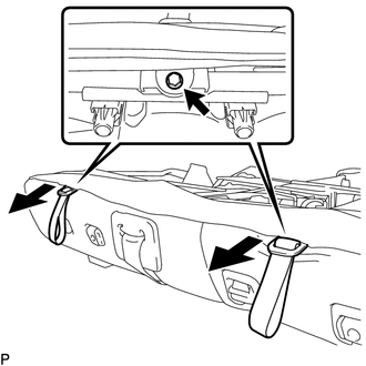
6. REMOVE TETHER ANCHOR BRACKET SUB-ASSEMBLY
|
Toyota Tundra Service Manual > Can Communication System: Check Bus 2 Lines for Short Circuit
DESCRIPTION There may be a short circuit between the CAN main bus lines when the resistance between terminals 18 (CA4H) and 17 (CA4L) of the central gateway ECU (network gateway ECU) is below 54 Ω. Symptom Trouble Area Resistance between terminals 18 (CA4H) and 17 (CA4L) of the central gateway ECU ...