INSPECTION
PROCEDURE
1. INSPECT FRONT SEAT INNER BELT ASSEMBLY LH (for Manual Seat)
|
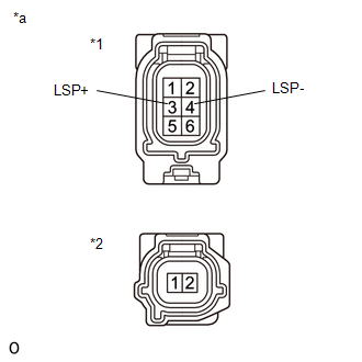
(a) Measure the resistance according to the value(s) in the table below.
Standard Resistance:
|
Tester Connection
|
Condition
|
Specified Condition
|
|
A-3 (LSP+) - B-1
|
Always
|
Below 1 Ω
|
|
A-4 (LSP-) - B-2
|
Always
|
Below 1 Ω
|
If the result is not as specified, replace the front seat inner belt
assembly LH.
Text in Illustration
|
*1
|
Connector A
|
|
*2
|
Connector B
|
|
*a
|
Component without harness connected
(Front Seat Inner Belt Assembly LH)
|
|
|
2. INSPECT FRONT SEAT INNER BELT ASSEMBLY LH (for Power Seat)
|
(a) for 8 Way Seat Type:
Measure the resistance according to the value(s) in the table below.
Standard Resistance:
|
Tester Connection
|
Condition
|
Specified Condition
|
|
A-3 (LSP+) - B-1
|
Always
|
Below 1 Ω
|
|
A-4 (LSP-) - B-2
|
Always
|
Below 1 Ω
|
If the result is not as specified, replace the front seat inner belt
assembly LH.
Text in Illustration
|
*1
|
Connector A
|
|
*2
|
Connector B
|
|
*a
|
Component without harness connected
(Front Seat Inner Belt Assembly LH)
|
|
|
|
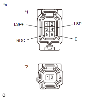
(b) for 10 Way Seat Type:
Measure the resistance according to the value(s) in the table below.
Standard Resistance:
|
Tester Connection
|
Condition
|
Specified Condition
|
|
A-3 (LSP+) - B-1
|
Always
|
Below 1 Ω
|
|
A-4 (LSP-) - B-2
|
Always
|
Below 1 Ω
|
|
A-5 (RDC) - A-6 (E)
|
Seat belt unfastened
|
Below 1 Ω
|
|
A-5 (RDC) - A-6 (E)
|
Seat belt fastened
|
10 kΩ or higher
|
If the result is not as specified, replace the front seat inner belt
assembly LH.
Text in Illustration
|
*1
|
Connector A
|
|
*2
|
Connector B
|
|
*a
|
Component without harness connected
(Front Seat Inner Belt Assembly LH)
|
|
|
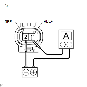
3. INSPECT FRONT SEAT INNER BELT ASSEMBLY RH
(a) Connect the battery and an ammeter to the front seat inner belt assembly
RH connector.
|
(b) Measure the current according to the value(s) in the table below.
Standard Current:
|
Tester Connection
|
Condition
|
Specified Condition
|
|
1 (RBE+) - 2 (RBE-)
|
Battery voltage is 12V
Seat belt unfastened
|
4.0 to 7.0 mA
|
|
1 (RBE+) - 2 (RBE-)
|
Battery voltage is 12V
Seat belt fastened
|
12 to 18 mA
|
If the result is not as specified, replace the front seat inner belt
assembly RH.
Text in Illustration
|
*a
|
Component without harness connected
(Front Seat Inner Belt Assembly RH)
|
|
|
|