Toyota Tundra Service Manual: Installation

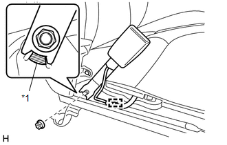
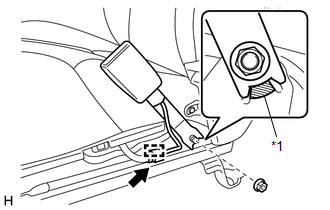
INSTALLATION

PROCEDURE

1. INSTALL FRONT SEAT INNER BELT ASSEMBLY LH

(a) for Manual Seat:

(1) Install the front seat inner belt assembly LH with the nut.

Torque:

42 N·m {428 kgf·cm, 31 ft·lbf}

NOTICE:

Do not allow the anchor of the front seat inner belt assembly LH to overlap the protruding part of the separate type front seat cushion spring assembly.

Text in Illustration

*1

Protruding Part

(2) Attach the wire harness clamp.

(3) Connect the connector and attach the connector clamp and 3 wire harness clamps.

Text in Illustration

*1

Connector Clamp

*2

Wire Harness Clamp

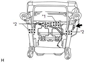
(4) Attach the 2 hooks of the separate type front seat cushion cover.

(b) for Power Seat:

(1) Install the front seat inner belt assembly LH with the nut.

Torque:

42 N·m {428 kgf·cm, 31 ft·lbf}

NOTICE:

Do not allow the anchor of the front seat inner belt assembly LH to overlap the protruding part of the separate type front seat cushion spring assembly.

Text in Illustration

*1

Protruding Part

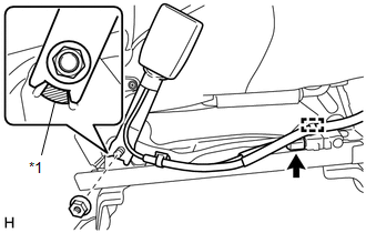
(2) Attach the wire harness clamp and connect the connector.

(3) Attach the connector clamp and 3 wire harness clamps.

Text in Illustration

*1

Connector Clamp

*2

Wire Harness Clamp

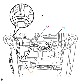
2. INSTALL FRONT SEAT INNER BELT ASSEMBLY RH

(a) Install the front seat inner belt assembly RH with the nut.

Torque:

42 N·m {428 kgf·cm, 31 ft·lbf}

NOTICE:

Do not allow the anchor of the front seat inner belt assembly RH to overlap the protruding part of the separate type front seat cushion spring assembly.

Text in Illustration

*1

Protruding Part

(b) Connect the connector and attach the connector clamp.

3. INSTALL FRONT SEAT CUSHION SHIELD LH (for Manual Seat, for Driver Side)

4. INSTALL RECLINING ADJUSTER RELEASE HANDLE LH (for Manual Seat, for Driver Side)

5. INSTALL FRONT SEAT ASSEMBLY (for Power Seat)

(See page )

6. INSTALL FRONT SEAT ASSEMBLY (for Manual Seat)

(See page )

7. CONNECT CABLE TO NEGATIVE BATTERY TERMINAL

NOTICE:

When disconnecting the cable, some systems need to be initialized after the cable is reconnected (See page ).

8. CHECK SRS WARNING LIGHT

Click here

    Inspection

    Removal

    See More:

    Toyota Tundra Service Manual > Sfi System: Secondary Air Injection System Switching Valve Stuck Open Bank1 (P2440-P2443)
    DESCRIPTION Refer to DTC P0412 (See page ). DTC No. DTC Detection Condition Trouble Area P2440 Cumulative pressure pulsation is 60 kPa (450 mmHg) or more for 2 seconds (1 trip detection logic). Air switching valve (ASV) assembly Open or short in ASV circuit Secondary air injection system piping Pres ...

    Toyota Tundra Owners Manual

    Toyota Tundra Service Manual

    © 2023 Copyright www.ttundra.com
    0.0091