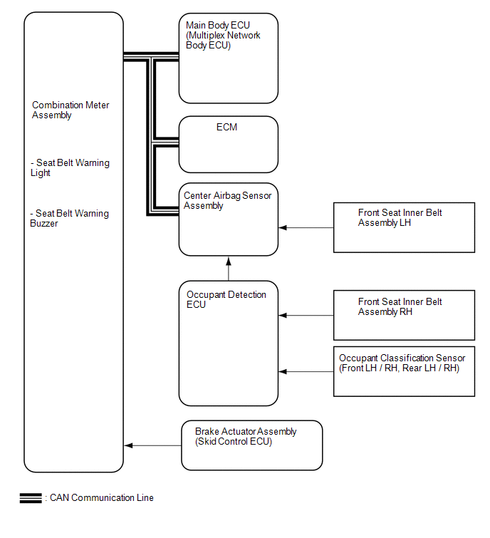
Toyota Tundra Service Manual: System Diagram

SYSTEM DIAGRAM

Communication Table

Sender

Receiver

Signal

Communication Method

Center airbag sensor assembly

Main body ECU (driver side junction block assembly)

Front seat inner belt assembly LH buckle switch

CAN

Combination meter assembly

  • Front seat inner belt assembly RH buckle switch
  • Occupant detection

Main Body ECU (Multiplex Network Body ECU)

Combination meter assembly

  • Front seat inner belt assembly LH buckle switch
  • Parking brake switch

ECM

Combination meter assembly

Shift position

    System Description

    Terminals Of Ecu

    See More:

    Toyota Tundra Service Manual > Vane Pump(for 1ur-fe): Disassembly
    DISASSEMBLY PROCEDURE 1. FIX VANE PUMP ASSEMBLY (a) Using SST, hold the vane pump in a vise. SST: 09630-00014 09631-00132 2. REMOVE POWER STEERING SUCTION PORT UNION (a) Remove the bolt and suction port union from the vane pump. (b) Using a screwdriver, remove the O-ring from the suction port union. ...

    Toyota Tundra Owners Manual

    Toyota Tundra Service Manual

    © 2026 Copyright www.ttundra.com
    0.0359