REMOVAL PROCEDURE 1. REMOVE SHIFT LEVER KNOB SUB-ASSEMBLY
2. REMOVE UPPER REAR CONSOLE PANEL SUB-ASSEMBLY
3. REMOVE UPPER CONSOLE PANEL SUB-ASSEMBLY
4. REMOVE REAR CONSOLE END PANEL SUB-ASSEMBLY
5. REMOVE CONSOLE BOX CARPET
6. REMOVE REAR CONSOLE BOX ASSEMBLY
7. REMOVE FRONT CONSOLE BOX
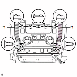
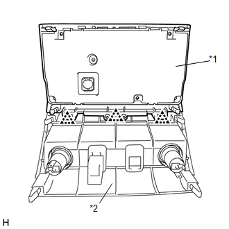
8. REMOVE AIR CONDITIONING CONTROL ASSEMBLY (CLIMATE CONTROL SEAT SWITCH)
(b) Using moulding remover B, detach the 8 clips, 2 claws and guide. (c) Disconnect each connector to remove the air conditioning control assembly (climate control seat switch) together with the center lower instrument panel finish panel.
|
Toyota Tundra Owners Manual > Specifications: Maintenance data
(fuel, oil level, etc.)
Dimensions 2WD models *1: Unladen vehicle *2: P255/70R18 tires *3: P275/65R18 tires *4: P275/55R20 tires 4WD models *1: Unladen vehicle *2: P255/70R18 tires *3: P275/65R18 tires *4: P275/55R20 tires Vehicle capacity weight Double Cab models *1: The model code is indicated on the Certification Label. ...