DESCRIPTION
When the position control ECU and switch assembly does not receive a sensor signal
despite forward or rearward movement of the seatback by power seat motor operation,
this DTC is stored.
|
DTC Code
|
DTC Detection Condition
|
Trouble Area
|
|
B2651
|
The forward and rearward lock detection position of the sensor is the
same.
|
- Position control ECU and switch assembly
- Front seatback frame sub-assembly LH (reclining motor)
- Harness or connector
|
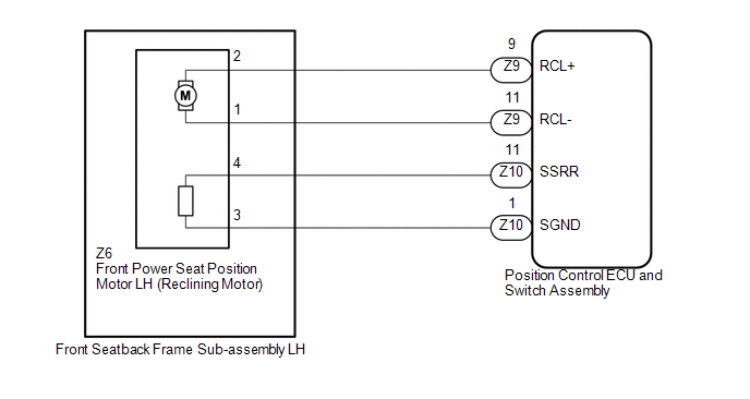
WIRING DIAGRAM
PROCEDURE
|
1.
|
PERFORM ACTIVE TEST USING TECHSTREAM (SEAT RECLINING)
|
(a) Connect the Techstream to the DLC3.
(b) Turn the ignition switch to ON.
(c) Turn the Techstream on.
(d) Enter the following menus: Body Electrical / Driver Seat / Active Test.
(e) Perform the Active Test according to the display on the Techstream.
Driver Seat
|
Tester Display
|
Test Part
|
Control Ranger
|
Diagnostic Note
|
|
Seat Reclining
|
Seat reclining operation
|
Front / OFF / Rear
|
-
|
OK:
Motor operates normally.
| NG |
 |
GO TO STEP 5
|
| OK |

|
|
|
2.
|
CHECK POSITION CONTROL ECU AND SWITCH ASSEMBLY (RECLINING MOTOR CIRCUIT)
|
|
(a) Disconnect the front seatback frame sub-assembly LH (reclining motor)
connector.
|
|
(b) Measure the voltage according to the value(s) in the table below.
Standard Voltage:
|
Tester Connection
|
Switch Condition
|
Specified Condition
|
|
Z6-4 - Z6-3
|
Reclining switch on
|
4.8 to 5.1 V
|
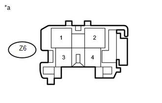
Text in Illustration
|
*a
|
Front view of wire harness connector
(to Front Seatback Frame Sub-assembly LH [Reclining Motor])
|
| NG |
|
GO TO STEP 4
|
| OK |
|
|
|
|
3.
|
CHECK FRONT SEATBACK FRAME SUB-ASSEMBLY LH (RECLINING MOTOR)
|
|
(a) Reconnect the front seatback frame sub-assembly LH (reclining motor)
connector.
|
|
(b) Measure the voltage according to the value(s) in the table below.
Standard Voltage:
|
Tester Connection
|
Switch Condition
|
Specified Condition
|
|
Z6-4 - Body ground
|
Reclining switch on
|
4.5 to 4.8 V
|
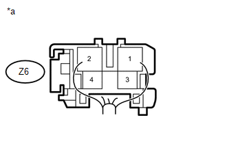
Text in Illustration
|
*a
|
Component with harness connected
(Front Seatback Frame Sub-assembly LH [Reclining Motor])
|
| OK |
|
REPLACE POSITION CONTROL ECU AND SWITCH ASSEMBLY
|
| NG |
|
REPLACE FRONT SEATBACK FRAME SUB-ASSEMBLY LH
|
|
4.
|
CHECK HARNESS AND CONNECTOR (POSITION CONTROL ECU AND SWITCH ASSEMBLY
- FRONT SEATBACK FRAME SUB-ASSEMBLY LH)
|
(a) Disconnect the Z10 position control ECU and switch assembly connector.
(b) Measure the resistance according to the value(s) in the table below.
Standard Resistance:
|
Tester Connection
|
Condition
|
Specified Condition
|
|
Z10-11 (SSRR) - Z6-4
|
Always
|
Below 1 Ω
|
|
Z10-1 (SGND) - Z6-3
|
Always
|
Below 1 Ω
|
|
Z10-11 (SSRR) or Z6-4 - Body ground
|
Always
|
10 kΩ or higher
|
|
Z10-1 (SGND) or Z6-3 - Body ground
|
Always
|
10 kΩ or higher
|
| OK |
|
REPLACE POSITION CONTROL ECU AND SWITCH ASSEMBLY
|
| NG |
|
REPAIR OR REPLACE HARNESS OR CONNECTOR
|
|
5.
|
INSPECT FRONT SEATBACK FRAME SUB-ASSEMBLY LH (RECLINING MOTOR)
|
(a) Remove the front seatback frame sub-assembly LH (reclining motor) (See page
 ). ).
(b) Inspect the front seatback frame sub-assembly LH (reclining motor) (See page
).
| NG |
|
REPLACE FRONT SEATBACK FRAME SUB-ASSEMBLY LH
|
| OK |
|
|
|
|
6.
|
CHECK HARNESS AND CONNECTOR (POSITION CONTROL ECU AND SWITCH ASSEMBLY
- FRONT SEATBACK FRAME SUB-ASSEMBLY LH)
|
(a) Disconnect the Z9 position control ECU and switch assembly connector.
(b) Measure the resistance according to the value(s) in the table below.
Standard Resistance:
|
Tester Connection
|
Condition
|
Specified Condition
|
|
Z9-9 (RCL+) - Z6-2
|
Always
|
Below 1 Ω
|
|
Z9-11 (RCL-) - Z6-1
|
Always
|
Below 1 Ω
|
|
Z9-9 (RCL+) or Z6-2 - Body ground
|
Always
|
10 kΩ or higher
|
|
Z9-11 (RCL-) or Z6-1 - Body ground
|
Always
|
10 kΩ or higher
|
| OK |
|
REPLACE POSITION CONTROL ECU AND SWITCH ASSEMBLY
|
| NG |
|
REPAIR OR REPLACE HARNESS OR CONNECTOR
|
|