1. CHECK POSITION CONTROL ECU AND SWITCH ASSEMBLY
(a) Disconnect the Z9 and Z10 position control ECU and switch assembly connectors.
(b) Measure the voltage and resistance according to the value(s) in the table
below.
(c) Reconnect the Z9 and Z10 position control ECU and switch assembly connectors.
(d) Measure the voltage and resistance according to the value(s) in the table
below.
|
Terminal No. (Symbols)
|
Wiring Color
|
Terminal Description
|
Condition
|
Specified Condition
|
|
Z9-1 (GND2) - Body ground
|
W-B - Body ground
|
Lumbar support adjuster ground
|
Always
|
Below 1 Ω
|
|
Z9-3 (SLD+) - Z9-2 (GND1)
|
L - W-B
|
Sliding motor signal (forward)
|
Seat moving forward using sliding switch
|
11 to 14 V
|
|
OFF
|
Below 1 V
|
|
Z9-4 (SLD-) - Z9-2 (GND1)
|
GR - W-B
|
Sliding motor signal (rearward)
|
Seat moving rearward using sliding switch
|
11 to 14 V
|
|
OFF
|
Below 1 V
|
|
Z9-5 (FRV-) - Z9-2 (GND1)
|
R - W-B
|
Front Vertical motor signal (downward)
|
Seat cushion front portion downward using front vertical switch
|
11 to 14 V
|
|
OFF
|
Below 1 V
|
|
Z9-6 (+B2) - Z9-1 (GND2)
|
LG - W-B
|
Lumbar support adjuster power source
|
Always
|
11 to 14 V
|
|
Z9-8 (FRV+) - Z9-2 (GND1)
|
B - W-B
|
Front vertical motor signal (upward)
|
Seat cushion front portion upward using front vertical switch
|
11 to 14 V
|
|
OFF
|
Below 1 V
|
|
Z9-9 (RCL+) - Z9-2 (GND1)
|
LG - W-B
|
Reclining motor signal (forward)
|
Seatback moving forward using reclining switch
|
11 to 14 V
|
|
OFF
|
Below 1 V
|
|
Z9-10 (LFT+) - Z9-2 (GND1)
|
V - W-B
|
Lift or motor signal (upward)
|
Seat cushion upward using lifter switch
|
11 to 14 V
|
|
OFF
|
Below 1 V
|
|
Z9-11 (RCL-) - Z9-2 (GND1)
|
P - W-B
|
Reclining motor signal (rearward)
|
Seatback moving rearward using reclining switch
|
11 to 14 V
|
|
OFF
|
Below 1 V
|
|
Z9-12 (LFT-) - Z9-2 (GND1)
|
Y - W-B
|
Lift or motor signal (downward)
|
Seat cushion downward using lifter switch
|
11 to 14 V
|
|
OFF
|
Below 1 V
|
|
Z10-1 (SGND) - Body ground
|
BR - Body ground
|
Position sensor ground
|
Always
|
Below 1 Ω
|
|
Z10-3 (SSFV) - Z10-1 (SGND)
|
R - BR
|
Vertical position signal
|
Front vertical function operation
|
4.5 to 4.8 V
|
|
Z10-4 (SSRL) - Z10-1 (SGND)
|
P - BR
|
Lift position signal
|
Lifter function operation
|
4.5 to 4.8 V
|
|
Z10-5 (SSRS) - Z10-1 (SGND)
|
G - BR
|
Slide position signal
|
Slide function operation
|
4.5 to 4.8 V
|
|
Z10-11 (SSRR) - Z10-1 (SGND)
|
O - BR
|
Reclining position signal
|
Reclining function operation
|
4.5 to 4.8 V
|
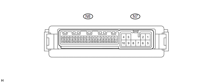
2. CHECK OUTER MIRROR CONTROL ECU ASSEMBLY
(a) Disconnect the N7 outer mirror control ECU assembly connector.
(b) Measure the voltage and resistance according to the value(s) in the table
below.
(c) Reconnect the N7 outer mirror control ECU assembly connector.
(d) Measure the voltage according to the value(s) in the table below.