INSPECTION
PROCEDURE
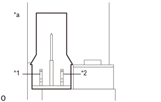
1. INSPECT FRONT SEATBACK FRAME SUB-ASSEMBLY LH (w/o Seat Position Memory System)
|
(a) Check the operation of the reclining motor LH.
(1) Apply battery voltage to the reclining motor LH connector, and check
that the reclining motor LH operates smoothly as follows.
OK:
|
Condition
|
Switch Condition
|
|
Battery positive (+) → Terminal 2
Battery negative (-) → Terminal 1
|
Forward
|
|
Battery positive (+) → Terminal 1
Battery negative (-) → Terminal 2
|
Backward
|
If the result is not as specified, replace the front seatback frame sub-assembly
LH.
Text in Illustration
|
*1
|
Terminal 1
|
|
*2
|
Terminal 2
|
|
*a
|
Component without wire harness connected
(Front Seatback Frame Sub-assembly LH (Reclining Motor LH))
|
|
|
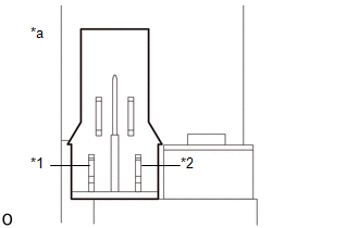
2. INSPECT FRONT SEATBACK FRAME SUB-ASSEMBLY LH (w/ Seat Position Memory System)
|
(a) Check the operation of the reclining motor LH.
(1) Apply battery voltage to the reclining motor LH connector, and check
that the reclining motor LH operates smoothly as follows.
OK:
|
Condition
|
Switch Condition
|
|
Battery positive (+) → Terminal 2
Battery negative (-) → Terminal 1
|
Forward
|
|
Battery positive (+) → Terminal 1
Battery negative (-) → Terminal 2
|
Backward
|
If the result is not as specified, replace the front seatback frame sub-assembly
LH.
Text in Illustration
|
*1
|
Terminal 1
|
|
*2
|
Terminal 2
|
|
*a
|
Component without wire harness connected
(Front Seatback Frame Sub-assembly LH (Reclining Motor LH))
|
|
|
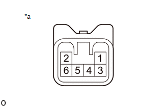
3. INSPECT FRONT SEAT CUSHION FRAME SUB-ASSEMBLY LH (w/o Seat Position Memory
System)
(a) Check the operation of the slide motor LH.
|
(1) Apply battery voltage to the slide motor LH connector, and check
that the slide motor LH operates smoothly as follows.
OK:
|
Condition
|
Switch Condition
|
|
Battery positive (+) → Terminal 4
Battery negative (-) → Terminal 3
|
Forward
|
|
Battery positive (+) → Terminal 3
Battery negative (-) → Terminal 4
|
Backward
|
If the result is not as specified, replace the front seat cushion frame
sub-assembly LH.
Text in Illustration
|
*a
|
Component without wire harness connected
(Front Seat Cushion Frame Sub-assembly LH (Slide Motor LH))
|
|
|
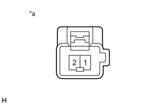
(b) Check the operation of the front vertical motor LH.
|
(1) Apply battery voltage to the front vertical motor LH connector, and
check that the front vertical motor LH operates smoothly as follows.
OK:
|
Condition
|
Switch Condition
|
|
Battery positive (+) → Terminal 2
Battery negative (-) → Terminal 1
|
Upward
|
|
Battery positive (+) → Terminal 1
Battery negative (-) → Terminal 2
|
Downward
|
If the result is not as specified, replace the front seat cushion frame
sub-assembly LH.
Text in Illustration
|
*1
|
Terminal 1
|
|
*2
|
Terminal 2
|
|
*a
|
Component without wire harness connected
(Front Seat Cushion Frame Sub-assembly LH (Front Vertical Motor
LH))
|
|
|
(c) Check the operation of the lifter motor LH.
|
(1) Apply battery voltage to the lifter motor LH connector, and check
that the lifter motor LH operates smoothly as follows.
OK:
|
Condition
|
Switch Condition
|
|
Battery positive (+) → Terminal 1
Battery negative (-) → Terminal 2
|
Upward
|
|
Battery positive (+) → Terminal 2
Battery negative (-) → Terminal 1
|
Downward
|
If the result is not as specified, replace the front seat cushion frame
sub-assembly LH.
Text in Illustration
|
*a
|
Component without wire harness connected
(Front Seat Cushion Frame Sub-assembly LH (Lifter Motor LH))
|
|
|
4. INSPECT FRONT SEAT CUSHION FRAME SUB-ASSEMBLY LH (w/ Seat Position Memory
System)
(a) Check the operation of the slide motor LH.
|
(1) Apply battery voltage to the slide motor LH connector, and check
that the slide motor LH operates smoothly as follows.
OK:
|
Condition
|
Switch Condition
|
|
Battery positive (+) → Terminal 4
Battery negative (-) → Terminal 3
|
Forward
|
|
Battery positive (+) → Terminal 3
Battery negative (-) → Terminal 4
|
Backward
|
If the result is not as specified, replace the front seat cushion frame
sub-assembly LH.
Text in Illustration
|
*a
|
Component without wire harness connected
(Front Seat Cushion Frame Sub-assembly LH (Slide Motor LH))
|
|
|
(b) Check the operation of the front vertical motor LH.
|
(1) Apply battery voltage to the front vertical motor LH connector, and
check that the front vertical motor LH operates smoothly as follows.
OK:
|
Condition
|
Switch Condition
|
|
Battery positive (+) → Terminal 2
Battery negative (-) → Terminal 1
|
Upward
|
|
Battery positive (+) → Terminal 1
Battery negative (-) → Terminal 2
|
Downward
|
If the result is not as specified, replace the front seat cushion frame
sub-assembly LH.
Text in Illustration
|
*1
|
Terminal 1
|
|
*2
|
Terminal 2
|
|
*a
|
Component without wire harness connected
(Front Seat Cushion Frame Sub-assembly LH (Front Vertical Motor
LH))
|
|
|
(c) Check the operation of the lifter motor LH.
|
(1) Apply battery voltage to the lifter motor LH connector, and check
that the lifter motor LH operates smoothly as follows.
OK:
|
Condition
|
Switch Condition
|
|
Battery positive (+) → Terminal 1
Battery negative (-) → Terminal 2
|
Upward
|
|
Battery positive (+) → Terminal 2
Battery negative (-) → Terminal 1
|
Downward
|
If the result is not as specified, replace the front seat cushion frame
sub-assembly LH.
Text in Illustration
|
*a
|
Component without wire harness connected
(Front Seat Cushion Frame Sub-assembly LH (Lifter Motor LH))
|
|
|
5. INSPECT FRONT SEAT CUSHION PANEL SUB-ASSEMBLY (w/ Leg Support Adjustment Switch)
|
(a) Check the operation of the leg support adjustment motor.
(1) Apply battery voltage to the leg support adjustment motor connector,
and check that the leg support adjustment motor operates smoothly as follows.
OK:
|
Condition
|
Switch Condition
|
|
Battery positive (+) → Terminal 2
Battery negative (-) → Terminal 1
|
Forward
|
|
Battery positive (+) → Terminal 1
Battery negative (-) → Terminal 2
|
Backward
|
If the result is not as specified, replace the front seat cushion panel
sub-assembly.
Text in Illustration
|
*a
|
Component without wire harness connected
(Front Seat Cushion Panel Sub-assembly (Leg Support Adjustment
Motor))
|
|
|
6. INSPECT FRONT SEATBACK FRAME SUB-ASSEMBLY RH
|
(a) Check the operation of the reclining motor RH.
(1) Apply battery voltage to the reclining motor RH connector, and check
that the reclining motor RH operates smoothly as follows.
OK:
|
Condition
|
Switch Condition
|
|
Battery positive (+) → Terminal 2
Battery negative (-) → Terminal 1
|
Forward
|
|
Battery positive (+) → Terminal 1
Battery negative (-) → Terminal 2
|
Backward
|
If the result is not as specified, replace the front seatback frame sub-assembly
RH.
Text in Illustration
|
*1
|
Terminal 1
|
|
*2
|
Terminal 2
|
|
*a
|
Component without wire harness connected
(Front Seatback Frame Sub-assembly RH (Reclining Motor RH))
|
|
|
7. INSPECT FRONT SEAT CUSHION FRAME SUB-ASSEMBLY RH
(a) Check the operation of the slide motor RH.
|
(1) Apply battery voltage to the slide motor RH connector, and check
that the slide motor RH operates smoothly as follows.
OK:
|
Condition
|
Switch Condition
|
|
Battery positive (+) → Terminal 4
Battery negative (-) → Terminal 3
|
Forward
|
|
Battery positive (+) → Terminal 3
Battery negative (-) → Terminal 4
|
Backward
|
If the result is not as specified, replace the front seat cushion frame
sub-assembly RH.
Text in Illustration
|
*a
|
Component without wire harness connected
(Front Seat Cushion Frame Sub-assembly RH (Slide Motor RH))
|
|
|
|