ON-VEHICLE INSPECTION PROCEDURE 1. REMOVE UPPER STEERING COLUMN COVER 2. REMOVE LOWER STEERING COLUMN COVER 3. INSPECT TILT MOTOR
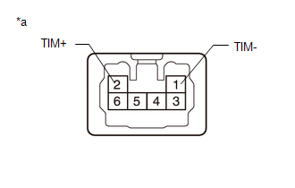
(b) Connect the positive (+) battery terminal to terminal 2 (TIM+) and the negative battery terminal to terminal 1 (TIM-) of the tilt motor connector. Then confirm that the steering wheel tilts up. OK: Steering wheel tilts up. (c) Connect the negative (-) battery terminal to terminal 2 (TIM+) and the positive battery terminal to terminal 1 (TIM-) of the tilt motor connector. Then confirm that the steering wheel tilts down. OK: Steering wheel tilts down. 4. INSPECT TELESCOPIC MOTOR
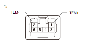
(b) Connect the positive battery terminal to terminal 1 (TEM+) and the negative battery terminal to terminal 2 (TEM-) of the telescopic motor connector. Then confirm that the steering column contracts. OK: Steering column contracts. (c) Connect the negative battery terminal to terminal 1 (TEM+) and the positive battery terminal to terminal 2 (TEM-) of the telescopic motor connector. Then confirm that the steering column extends. OK: Steering column extends. 5. INSTALL LOWER STEERING COLUMN COVER 6. INSTALL UPPER STEERING COLUMN COVER |
Toyota Tundra Service Manual > Blind Spot Monitor System: Slave Module Horizontal Axis Misalignment (C1AC2)
DESCRIPTION This DTC is stored when the angle of the blind spot monitor sensor LH deviates more than the allowable range from the horizontal axis. HINT: If a drum tester such as a speedometer tester, brake/speedometer combination tester or chassis dynamometer is used with the blind spot monitor syst ...