INSPECTION
PROCEDURE
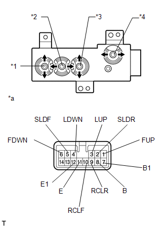
1. INSPECT FRONT POWER SEAT SWITCH LH
(a) Check the resistance of the front power seat switch LH.
|
(1) Measure the resistance according to the value(s) in the table below.
Standard Resistance:
Slide Switch
|
Tester Connection
|
Switch Condition
|
Specified Condition
|
|
5 (SLDF) - 8 (B)
5 (SLDF) - 7 (B1)
|
Front position
|
Below 1 Ω
|
|
2 (SLDR) - 11 (E)
2 (SLDR) - 12 (E1)
|
|
5 (SLDF) - 11 (E)
5 (SLDF) - 12 (E1)
|
Neutral
|
|
2 (SLDR) - 11 (E)
2 (SLDR) - 12 (E1)
|
|
5 (SLDF) - 11 (E)
5 (SLDF) - 12 (E1)
|
Rear position
|
|
2 (SLDR) - 8 (B)
2 (SLDR) - 7 (B1)
|
Front Vertical Switch
|
Tester Connection
|
Switch Condition
|
Specified Condition
|
|
1 (FUP) - 8 (B)
1 (FUP) - 7 (B1)
|
Up position
|
Below 1 Ω
|
|
6 (FDWN) - 11 (E)
6 (FDWN) - 12 (E1)
|
|
1 (FUP) - 11 (E)
1 (FUP) - 12 (E1)
|
Neutral
|
|
6 (FDWN) - 11 (E)
6 (FDWN) - 12 (E1)
|
|
1 (FUP) - 11 (E)
1 (FUP) - 12 (E1)
|
Down position
|
|
6 (FDWN) - 8 (B)
6 (FDWN) - 7 (B1)
|
Lifter Switch
|
Tester Connection
|
Switch Condition
|
Specified Condition
|
|
3 (LUP) - 8 (B)
3 (LUP) - 7 (B1)
|
Up position
|
Below 1 Ω
|
|
4 (LDWN) - 11 (E)
4 (LDWN) - 12 (E1)
|
|
3 (LUP) - 11 (E)
3 (LUP) - 12 (E1)
|
Neutral
|
|
4 (LDWN) - 11 (E)
4 (LDWN) - 12 (E1)
|
|
3 (LUP) - 11 (E)
3 (LUP) - 12 (E1)
|
Down position
|
|
4 (LDWN) - 8 (B)
4 (LDWN) - 7 (B1)
|
Reclining Switch
|
Tester Connection
|
Switch Condition
|
Specified Condition
|
|
8 (B) - 10 (RCLF)
7 (B1) - 10 (RCLF)
|
Front position
|
Below 1 Ω
|
|
9 (RCLR) - 11 (E)
9 (RCLR) - 12 (E1)
|
|
10 (RCLF) - 11 (E)
10 (RCLF) - 12 (E1)
|
Neutral
|
|
9 (RCLR) - 11 (E)
9 (RCLR) - 12 (E1)
|
|
10 (RCLF) - 11 (E)
10 (RCLF) - 12 (E1)
|
Rear position
|
|
8 (B) - 9 (RCLR)
7 (B1) - 9 (RCLR)
|
If the result is not as specified, replace the front power seat switch
LH.
Text in Illustration
|
*1
|
Front Vertical Switch
|
|
*2
|
Slide Switch
|
|
*3
|
Lifter Switch
|
|
*4
|
Reclining Switch
|
|
*a
|
Component without harness connected
(Front Power Seat Switch LH)
|
|
|
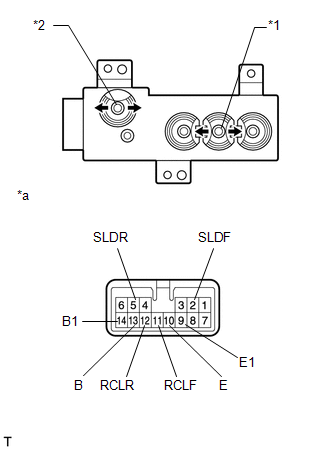
2. INSPECT FRONT POWER SEAT SWITCH RH
(a) Check the resistance of the front power seat switch RH.
|
(1) Measure the resistance according to the value(s) in the table below.
Standard Resistance:
Slide Switch
|
Tester Connection
|
Switch Condition
|
Specified Condition
|
|
2 (SLDF) - 13 (B)
2 (SLDF) - 14 (B1)
|
Front position
|
Below 1 Ω
|
|
5 (SLDR) - 10 (E)
5 (SLDR) - 9 (E1)
|
|
2 (SLDF) - 10 (E)
2 (SLDF) - 9 (E1)
|
Neutral
|
|
5 (SLDR) - 10 (E)
5 (SLDR) - 9 (E1)
|
|
2 (SLDF) - 10 (E)
2 (SLDF) - 9 (E1)
|
Rear position
|
|
5 (SLDR) - 13 (B)
5 (SLDR) - 14 (B1)
|
Reclining Switch
|
Tester Connection
|
Switch Condition
|
Specified Condition
|
|
11 (RCLF) - 13 (B)
11 (RCLF) - 14 (B1)
|
Front position
|
Below 1 Ω
|
|
10 (E) - 12 (RCLR)
9 (E1) - 12 (RCLR)
|
|
10 (E) - 11 (RCLF)
9 (E1) - 11 (RCLF)
|
Neutral
|
|
12 (RCLR) - 10 (E)
12 (RCLR) - 9 (E1)
|
|
10 (E) - 11 (RCLF)
9 (E1) - 11 (RCLF)
|
Rear position
|
|
12 (RCLR) - 13 (B)
12 (RCLR) - 14 (B1)
|
If the result is not as specified, replace the front power seat switch.
Text in Illustration
|
*1
|
Slide Switch
|
|
*2
|
Reclining Switch
|
|
*a
|
Component without harness connected
(Front Power Seat Switch RH)
|
|
|
|