Components COMPONENTS ILLUSTRATION 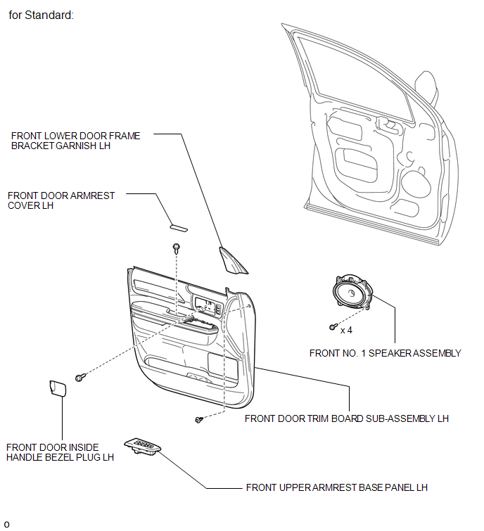 ILLUSTRATION 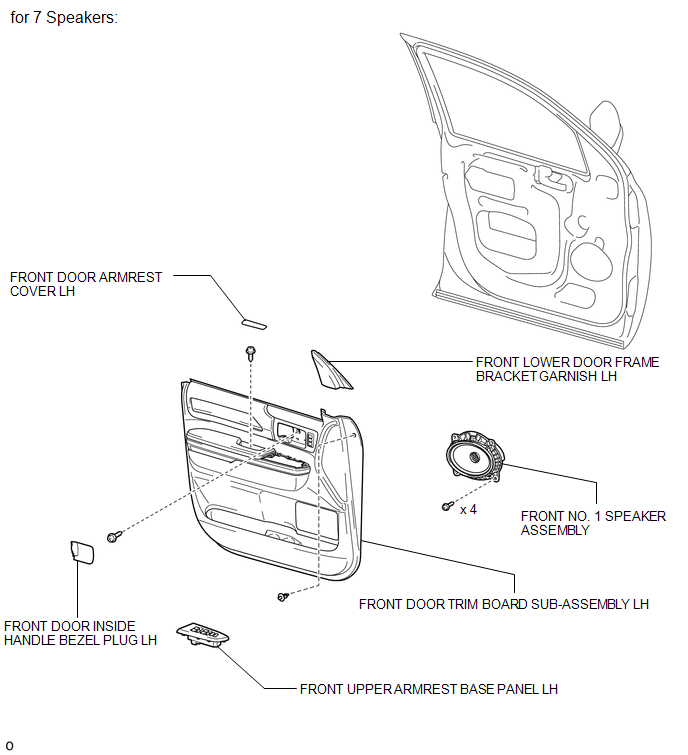 Inspection INSPECTION PROCEDURE 1. INSPECT FRONT NO. 1 SPEAKER ASSEMBLY (for Standard) 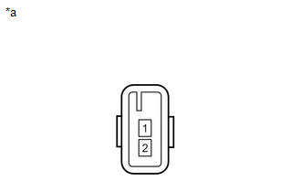 (a) Measure the resistance according to the value(s) in the table below. Standard resistance:
If the result is not as specified, replace the front No. 1 speaker assembly. Text in Illustration
2. INSPECT FRONT NO. 1 SPEAKER ASSEMBLY (for 7 Speakers) (a) Measure the resistance according to the value(s) in the table below. Standard resistance:
If the result is not as specified, replace the front No. 1 speaker assembly. Text in Illustration
Installation INSTALLATION CAUTION / NOTICE / HINT HINT:
PROCEDURE 1. INSTALL FRONT NO. 1 SPEAKER ASSEMBLY (a) Connect the connector. (b) Install the front No. 1 speaker assembly with the 4 screws. 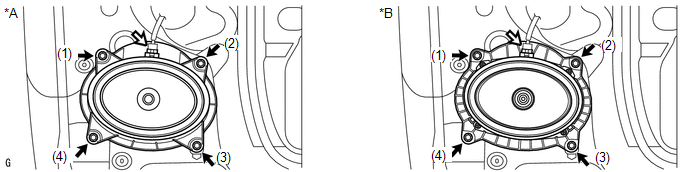 Text in Illustration Text in Illustration
NOTICE: Do not touch the cone part of the speaker. HINT: Install the screws in the order shown in the illustration. 2. INSTALL FRONT DOOR TRIM BOARD SUB-ASSEMBLY LH 3. INSTALL FRONT DOOR ARMREST COVER LH 4. INSTALL FRONT UPPER ARMREST BASE PANEL LH
5. INSTALL FRONT DOOR INSIDE HANDLE BEZEL PLUG LH 6. INSTALL FRONT LOWER DOOR FRAME BRACKET GARNISH LH Removal REMOVAL CAUTION / NOTICE / HINT HINT:
PROCEDURE 1. REMOVE FRONT LOWER DOOR FRAME BRACKET GARNISH LH 2. REMOVE FRONT DOOR INSIDE HANDLE BEZEL PLUG LH 3. REMOVE FRONT UPPER ARMREST BASE PANEL LH 4. REMOVE FRONT DOOR ARMREST COVER LH 5. REMOVE FRONT DOOR TRIM BOARD SUB-ASSEMBLY LH
6. REMOVE FRONT NO. 1 SPEAKER ASSEMBLY (a) Remove the 4 screws. 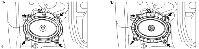 Text in Illustration Text in Illustration
NOTICE: Do not touch the cone part of the speaker. (b) Disconnect the connector and remove the front No. 1 speaker assembly. |
Toyota Tundra Service Manual > Navigation System: Cursor or Map Rotates when Vehicle Stopped
PROCEDURE 1. CHECK CONDITION (a) Check with the customer if the vehicle has been turned by a turntable. OK: Vehicle has not been turned by a turntable. HINT: If the vehicle is turned on a turntable with the ignition switch to ON, the system may store the angular velocity. As a result, the vehicle po ...


