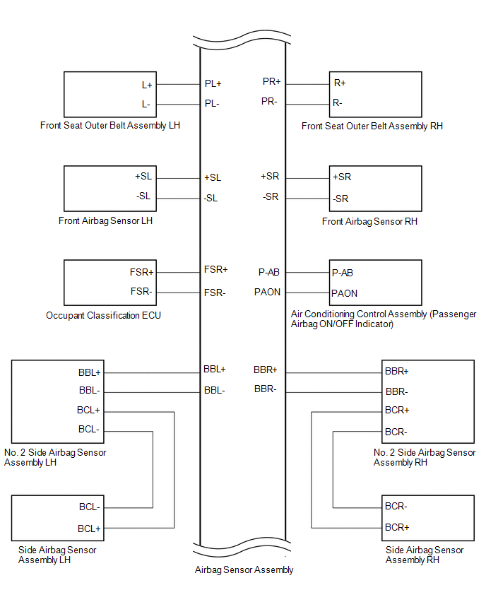
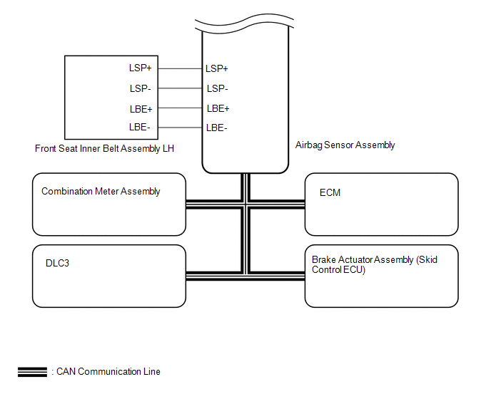
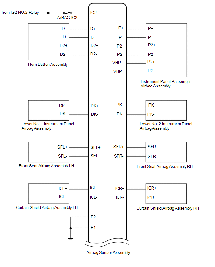
Toyota Tundra Service Manual: System Diagram

SYSTEM DIAGRAM

Communication Table

Transmitting ECU

(Transmitter)

Receiving ECU

(Receiver)

Signal

Communication Method

Airbag Sensor Assembly

ECM

Crash detection signal

CAN

Brake Actuator Assembly (Skid Control ECU)

Combination Meter Assembly

  • SRS warning light on demand signal
  • SRS warning light blink demand signal
    System Description

    Terminals Of Ecu

    See More:

    Toyota Tundra Service Manual > Air Conditioning System(for Automatic Air Conditioning System): Evaporator Temperature Sensor Circuit (B1413/13)
    DESCRIPTION The No. 1 cooler thermistor is installed on the evaporator in the air conditioner unit to detect the cooled air temperature that has passed through the evaporator and control the air conditioning. It sends appropriate signals to the air conditioning amplifier. The resistance of the No. 1 ...

    Toyota Tundra Owners Manual

    Toyota Tundra Service Manual

    © 2026 Copyright www.ttundra.com
    0.0333