REMOVAL PROCEDURE 1. REMOVE FRONT PILLAR GARNISH LH 2. REMOVE FRONT PILLAR GARNISH RH 3. REMOVE NO. 1 INSTRUMENT PANEL SPEAKER PANEL SUB-ASSEMBLY 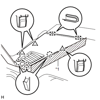 Text in Illustration Text in Illustration
(a) Apply protective tape as shown in the illustration. (b) Using moulding remover B, detach the 3 clips, 3 claws and 2 guides and remove the No. 1 instrument panel speaker panel sub-assembly. 4. REMOVE NO. 2 INSTRUMENT PANEL SPEAKER PANEL SUB-ASSEMBLY 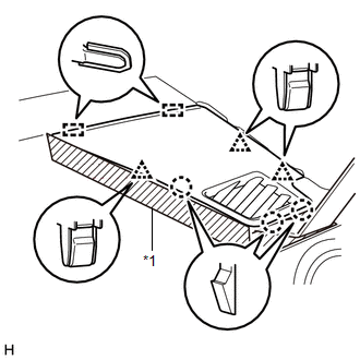 Text in Illustration Text in Illustration
(a) Apply protective tape as shown in the illustration. (b) Using moulding remover B, detach the 3 clips, 3 claws and 2 guides and remove the No. 2 instrument panel speaker panel sub-assembly. 5. REMOVE FRONT NO. 2 SPEAKER ASSEMBLY LH (a) Remove the 2 bolts. 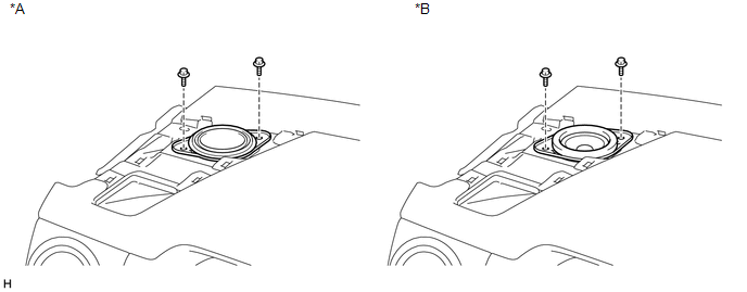 Text in Illustration Text in Illustration
(b) Disconnect the connector and remove the front No. 2 speaker assembly LH. NOTICE: Do not touch the cone part of the speaker. 6. REMOVE FRONT NO. 2 SPEAKER ASSEMBLY RH 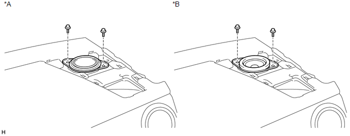 Text in Illustration Text in Illustration
(a) Remove the 2 bolts. (b) Disconnect the connector and remove the front No. 2 speaker assembly RH. NOTICE: Do not touch the cone part of the speaker. 7. REMOVE NO. 1 SPEAKER HOLE COVER 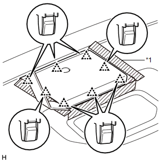 Text in Illustration Text in Illustration
(a) Apply protective tape as shown in the illustration. (b) Using moulding remover B, detach the 8 clips and remove the No. 1 speaker hole cover. 8. REMOVE FRONT NO. 4 SPEAKER ASSEMBLY (for 7 Speakers) 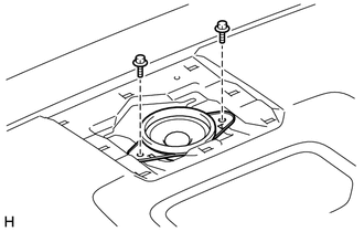 (a) Remove the 2 bolts. (b) Disconnect the connector and remove the front No. 4 speaker assembly. NOTICE: Do not touch the cone part of the speaker. |
Toyota Tundra Service Manual > Air Conditioning System(for Automatic Air Conditioning System): Air Inlet Damper Control Servo Motor Circuit (B1442/42)
DESCRIPTION The air inlet damper servo motor sends pulse signals to inform the air conditioning amplifier of the damper position. The air conditioning amplifier activates the motor (normal, reverse) based on the signals to move the air inlet damper to any position, which controls the intake air sett ...


