Components COMPONENTS ILLUSTRATION 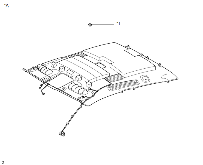
ILLUSTRATION 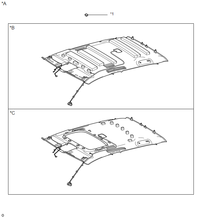
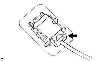
Installation INSTALLATION PROCEDURE 1. INSTALL TELEPHONE MICROPHONE ASSEMBLY
(b) Connect the connector. 2. INSTALL ROOF HEADLINING ASSEMBLY (a) for Double Cab: Click here (b) for CrewMax: Click here
Removal REMOVAL PROCEDURE 1. REMOVE ROOF HEADLINING ASSEMBLY (a) for Double Cab: Click here
(b) for CrewMax: Click here
2. REMOVE TELEPHONE MICROPHONE ASSEMBLY
(b) Detach the 2 claws and remove the telephone microphone assembly. |
Toyota Tundra Service Manual > Navigation System: Satellite Radio Broadcast cannot be Received
CAUTION / NOTICE / HINT NOTICE: Some satellite radio broadcasts require payment. A contract must be made between a satellite radio company and the user. If the contract expires, it will not be possible to listen to the broadcast. After replacing the stereo component tuner assembly of vehicles subscr ...