Toyota Tundra Service Manual: Radio Antenna Pole

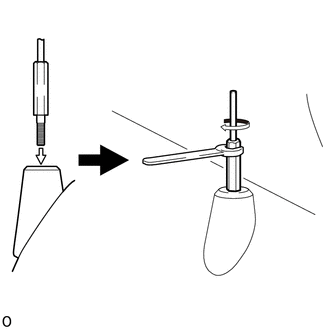
Components

COMPONENTS

ILLUSTRATION

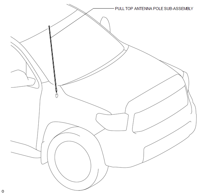
Installation

INSTALLATION

PROCEDURE

1. INSTALL PULL TOP ANTENNA POLE SUB-ASSEMBLY

(a) Install the pull top antenna pole sub-assembly and tighten it by hand until it is fully seated.

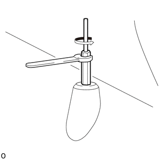
(b) Using an 8 mm (0.315 in.) wrench or antenna mast tool, tighten the pull top antenna pole sub-assembly clockwise approximately 1/8 turn (20 to 45 degrees).

HINT:

  • Do not overtighten the pull top antenna pole sub-assembly. Tighten the pull top antenna pole sub-assembly with your fingers, not your whole hand.
  • Do not use pliers to tighten the pull top antenna pole sub-assembly as it can leave marks on the pull top antenna pole sub-assembly surface.
  • The pull top antenna pole sub-assembly cannot be tightened by hand to the proper torque specification.

Torque:

3.3 N·m {3.4 kgf·cm, 29 in·lbf}

Removal

REMOVAL

PROCEDURE

1. REMOVE PULL TOP ANTENNA POLE SUB-ASSEMBLY

(a) Using an 8 mm (0.315 in.) wrench or antenna mast tool, remove the pull top antenna pole sub-assembly by turning it counterclockwise.

    Microphone Amplifier

    Radio Antenna

    See More:

    Toyota Tundra Service Manual > Engine Immobiliser System (w/o Smart Key System): Parts Location
    PARTS LOCATION ILLUSTRATION *1 UNLOCK WARNING SWITCH ASSEMBLY *2 TRANSPONDER KEY COIL *3 TRANSPONDER KEY ECU ASSEMBLY *4 ECM *5 COMBINATION METER ASSEMBLY (SECURITY INDICATOR LIGHT) *6 MAIN BODY ECU (MULTIPLEX NETWORK BODY ECU) *7 DRIVER SIDE JUNCTION BLOCK ASSEMBLY - ECU-B NO.1 FUSE - ECU-IG2 NO.3 ...

    Toyota Tundra Owners Manual

    Toyota Tundra Service Manual

    © 2024 Copyright www.ttundra.com
    0.0102