INSTALLATION PROCEDURE 1. INSTALL FENDER ANTENNA ASSEMBLY (a) Install the fender antenna assembly with the bolt. Torque: 9.0 N·m {92 kgf·cm, 80 in·lbf} (b) Attach the 5 clamps and install the bolt. Torque: 9.0 N·m {92 kgf·cm, 80 in·lbf} (c) Connect each connector. 2. INSTALL FRONT FENDER LINER RH 3. INSTALL SIDE STEP ASSEMBLY RH (w/ Side Step)
4. INSTALL FRONT FENDER MUDGUARD RH (w/ Front Fender Mudguard) 5. INSTALL ANTENNA ORNAMENT 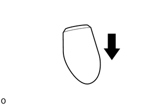 (a) Install the antenna ornament as shown in the illustration. 6. INSTALL INSTRUMENT PANEL SUB-ASSEMBLY (a) for Column Shift Type: (See page (b) for Floor Shift Type: (See page 7. CONNECT CABLE TO NEGATIVE BATTERY TERMINAL NOTICE: When disconnecting the cable, some systems need to be initialized after the cable is reconnected (See page
8. CHECK SRS WARNING LIGHT (See page 9. INSTALL PULL TOP ANTENNA POLE SUB-ASSEMBLY (See page
|
Toyota Tundra Service Manual > Front Seat Assembly(for Manual Seat): Disassembly
DISASSEMBLY CAUTION / NOTICE / HINT CAUTION: Wear protective gloves. Sharp areas on the parts may injure your hands. HINT: Use the same procedure for the RH and LH sides. The procedure listed below is for the LH side. PROCEDURE 1. REMOVE RECLINING ADJUSTER RELEASE HANDLE LH (a) Raise the reclining a ...


