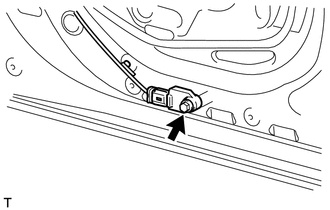
INSTALLATION PROCEDURE 1. INSTALL FRONT SIDE AIRBAG SENSOR
(b) Check that the cable is disconnected from the battery negative (-) terminal. CAUTION: Wait at least 90 seconds after disconnecting the cable from the negative (-) battery terminal to prevent airbag and seat belt pretensioner activation. (c) Install the door airbag sensor with the screw. Torque: 9.0 N·m {92 kgf·cm, 80 in·lbf} NOTICE:
(d) Check that there is no looseness in the installation parts of the door airbag sensor. (e) Connect the connector. 2. INSTALL FRONT DOOR TRIM BOARD SUB-ASSEMBLY LH (for Front Side)
3. INSTALL FRONT LOWER DOOR FRAME BRACKET GARNISH LH (for Front Side)
4. INSTALL FRONT UPPER ARMREST BASE PANEL LH (for Front Side)
5. INSTALL FRONT DOOR INSIDE HANDLE BEZEL PLUG LH (for Front Side)
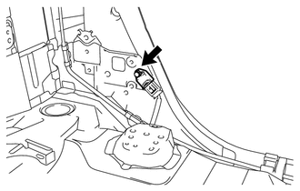
6. INSTALL REAR SIDE AIRBAG SENSOR
(b) Check that the cable is disconnected from the battery negative (-) terminal. CAUTION: Wait at least 90 seconds after disconnecting the cable from the negative (-) battery terminal to prevent airbag and seat belt pretensioner activation. (c) Install the side airbag sensor with the bolt. Torque: 9.0 N·m {92 kgf·cm, 80 in·lbf} NOTICE:
(d) Check that there is no looseness in the installation parts of the side airbag sensor. (e) Connect the connector. 7. INSTALL LOWER QUARTER TRIM PANEL ASSEMBLY LH (for Rear Side)
8. INSTALL REAR DOOR OPENING TRIM WEATHERSTRIP LH (for Rear Side) 9. INSTALL REAR DOOR SCUFF PLATE LH (for Rear Side)
10. INSTALL REAR SEAT ASSEMBLY (for Rear Side) (a) Install the rear seat assembly (see page 11. CONNECT CABLE TO NEGATIVE BATTERY TERMINAL NOTICE: When disconnecting the cable, some systems need to be initialized after the cable
is reconnected (See page 12. CHECK SRS WARNING LIGHT (a) Check the SRS warning light (see page |
Toyota Tundra Service Manual > Sfi System: Problem Symptoms Table
PROBLEM SYMPTOMS TABLE Use the table below to help determine the cause of problem symptoms. If multiple suspected areas are listed, the potential causes of the symptoms are listed in order of probability in the "Suspected Area" column of the table. Check each symptom by checking the suspected areas ...