DESCRIPTION When the theft deterrent system is switched from the armed state to the alarm sounding state, the main body ECU (multiplex network body ECU) transmits a signal to cause the horn to sound at intervals of 0.4 seconds. WIRING DIAGRAM 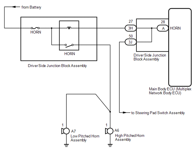
CAUTION / NOTICE / HINT NOTICE: Inspect the fuses for circuits related to this system before performing the following procedure. PROCEDURE
(a) Press the horn switch and check if the horns sound. Result
(a) Remove the driver side junction block assembly. Click here
|
Toyota Tundra Service Manual > Steering Gear: Disassembly
DISASSEMBLY PROCEDURE 1. FIX POWER STEERING GEAR ASSEMBLY (a) Using SST, secure the power steering gear. SST: 09612-00012 HINT: Tape SST before use. NOTICE: When using a vise, do not overtighten it. 2. REMOVE TIE ROD END SUB-ASSEMBLY LH (a) Put matchmarks on the tie rod end LH and steering rack end. ...