DESCRIPTION When the glass breakage sensor detects the glass is broken (1st time), the sensor will set off an alarm for 20 seconds (pre-alarm). If the glass breakage sensor detects that more glass is broken (2nd time or more), the sensor will set off an alarm for 60 seconds. WIRING DIAGRAM 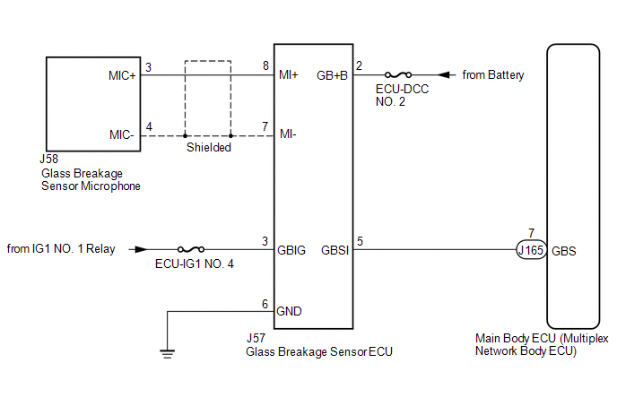
CAUTION / NOTICE / HINT NOTICE: Inspect the fuses for circuits related to this system before performing the following procedure. PROCEDURE
(a) Connect the Techstream to the DLC3. (b) Turn the ignition switch to ON. (c) Turn the Techstream on. (d) Enter the following menus: Body Electrical / Main Body / Data List. (e) Read the Data List according to the display on the Techstream. Body Electrical > Main Body > Data List
OK: When tapping on the door glass with your finger, "ON" is displayed on the Techstream screen.
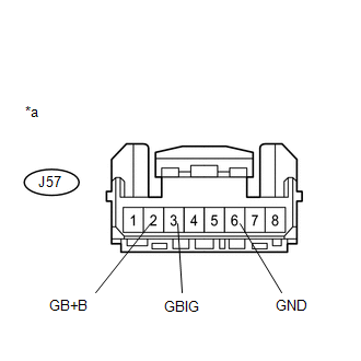
(b) Measure the voltage according to the value(s) in the table below. Standard Voltage:
(c) Measure the resistance according to the value(s) in the table below. Standard Resistance:
(a) Disconnect the J165 main body ECU (multiplex network body ECU) connector. (b) Disconnect the J57 glass breakage sensor ECU connector. (c) Measure the resistance according to the value(s) in the table below. Standard Resistance:
(a) Disconnect the J57 glass breakage sensor ECU connector. (b) Disconnect the J58 glass breakage sensor microphone connector. (c) Measure the resistance according to the value(s) in the table below. Standard Resistance:
(a) Turn the ignition switch to ON. (b) Using an oscilloscope, check the waveform. 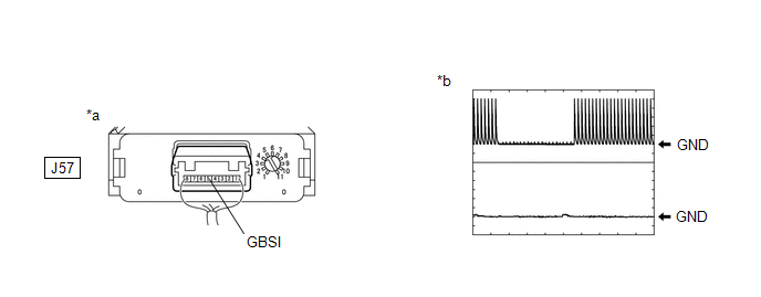
Standard:
(a) Temporarily replace the glass breakage sensor microphone with a new or normally functioning one.
(a) Turn the ignition switch to ON. (b) Using an oscilloscope, check the waveform. 
Standard:
|
Toyota Tundra Service Manual > Air Conditioning System(for Automatic Air Conditioning System): Ambient Temperature Sensor Circuit (B1412/12)
DESCRIPTION The ambient temperature sensor is installed in front of the condenser to detect the ambient temperature which is used to control the air conditioner "AUTO" mode. This sensor is connected to the air conditioning amplifier and detects fluctuations in the ambient temperature. This ...