DESCRIPTION When the theft deterrent system is in the disarmed state, the security indicator light will blink if the immobiliser system is set, or not illuminate if the immobiliser system is not set. When the theft deterrent system is in the armed state, the security indicator light blinks. When the theft deterrent system is in the arming preparation state or alarm sounding state, the security indicator light illuminates. WIRING DIAGRAM 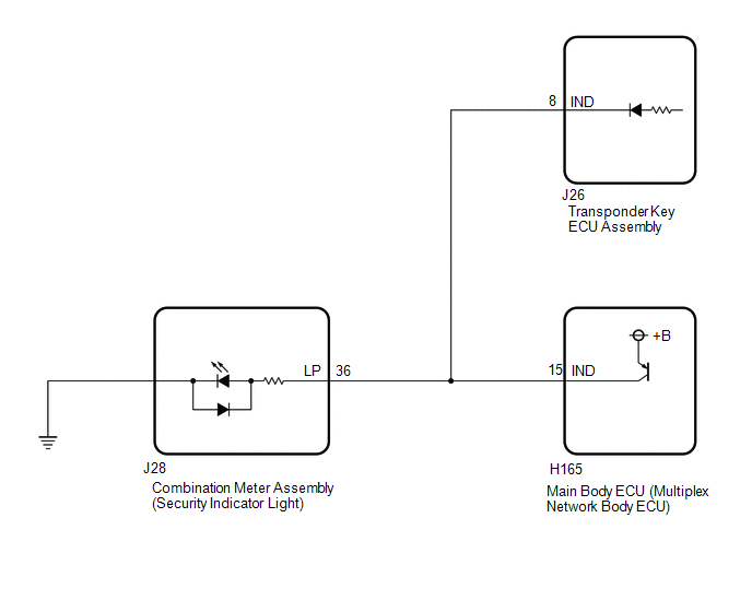
CAUTION / NOTICE / HINT NOTICE: Before performing the inspection, check "Security Indicator Light Does not Blink" in ENGINE IMMOBILISER SYSTEM. Click here PROCEDURE
(a) Connect the Techstream to the DLC3. (b) Turn the ignition switch to ON. (c) Turn the Techstream on. (d) Enter the following menus: Body Electrical / Main Body / Active Test. (e) According to the display on the Techstream, perform the Active Test. Body Electrical > Main Body > Data List
OK: The theft warning siren assembly sounds and stops correctly when operated through the Techstream.
(a) Disconnect the J28 combination meter assembly (security indicator light) connector. (b) Disconnect the J165 main body ECU (multiplex network body ECU) connector. (c) Disconnect the J26 transponder key ECU assembly connector. (d) Measure the resistance according to the value(s) in the table below. Standard Resistance:
|
Toyota Tundra Service Manual > Sliding Roof Housing(for Crewmax): Installation
INSTALLATION PROCEDURE 1. INSTALL SLIDING ROOF HOUSING SUB-ASSEMBLY (a) Temporarily install the housing with the 10 bolts (vehicle body side) and 6 nuts. (b) Tighten the 6 nuts. Torque: 5.5 N·m {56 kgf·cm, 49 in·lbf} (c) Tighten the 10 bolts. Torque: 5.5 N·m {56 kgf·cm, 49 in·lbf} (d) Connect ...


