DESCRIPTION When the theft deterrent system is switched from the armed state to the alarm sounding state, the main body ECU (multiplex network body ECU) transmits a signal to cause the security horn to sound at intervals of 0.4 seconds. WIRING DIAGRAM 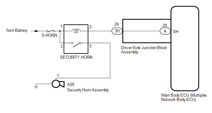
CAUTION / NOTICE / HINT NOTICE:
PROCEDURE
(a) Connect the Techstream to the DLC3. (b) Turn the ignition switch to ON. (c) Turn the Techstream on. (d) Enter the following menus: Body Electrical / Main Body / Active Test. (e) According to the display on the Techstream, perform the Active Test. Main Body
OK: The security horn assembly sounds and stops correctly when operated through the Techstream.
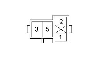
(a) Remove the security horn assembly. Click here (b) Inspect the security horn assembly. Click here
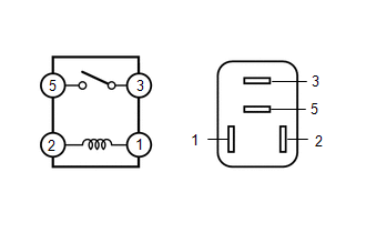
(b) Measure the resistance according to the value(s) in the table below. Standard Resistance:
(a) Remove the main body ECU (multiplex network body ECU). Click here (b) Connect the driver side junction block assembly connectors. (c) Remove the SECURITY HORN relay. (d) Measure the resistance according to the value(s) in the table below. Standard Resistance:
(b) Measure the voltage according to the value(s) in the table below. Standard Voltage:
(a) Remove the SECURITY HORN relay. (b) Disconnect the A28 security horn assembly connector. (c) Measure the resistance according to the value(s) in the table below. Standard Resistance:
(a) Disconnect the 3H driver side junction block assembly connector. (b) Remove the SECURITY HORN relay. (c) Measure the resistance according to the value(s) in the table below. Standard Resistance:
|
Toyota Tundra Service Manual > Tire Pressure Warning System: Operation Check
OPERATION CHECK CHECK TIRE PRESSURE WARNING SYSTEM FUNCTION (a) Using the Data List, check that the current tire pressure is normal. Click here (1) Slowly reduce the tire pressure of the front or rear tires and check that the tire pressure on the Data List changes. HINT: For this vehicle, data recep ...