1. CHECK DRIVER SIDE JUNCTION BLOCK ASSEMBLY, MAIN BODY ECU (MULTIPLEX NETWORK
BODY ECU)
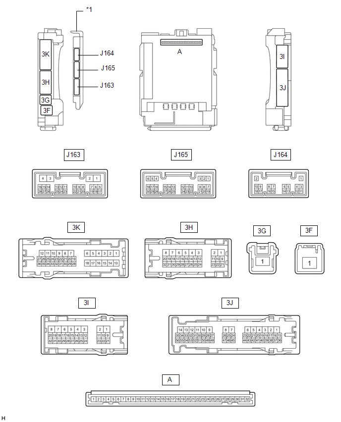
(a) Remove the main body ECU (multiplex network body ECU) from the driver side
junction block assembly.
(b) Connect the driver side junction block assembly connectors.
(c) Measure the voltage and resistance according to the value(s) in the table
below.
|
Tester Connection
|
Wiring Color
|
Terminal Description
|
Condition
|
Specified Condition
|
|
A-32 (IG) - Body ground
|
None - Body ground
|
Ignition power supply
|
Ignition switch ON
|
11 to 14 V
|
|
Ignition switch off
|
Below 1 V
|
|
A-31 (BECU) - Body ground
|
None - Body ground
|
Battery power supply
|
Always
|
11 to 14 V
|
|
A-30 (ACC) - Body ground
|
None - Body ground
|
ACC power supply
|
Ignition switch ACC
|
11 to 14 V
|
|
Ignition switch off
|
Below 1 V
|
|
A-11 (GND1) - Body ground
|
None - Body ground
|
Ground
|
Always
|
Below 1 Ω
|
|
J165-6 (FLCY) - Body ground
|
GR - Body ground
|
Front courtesy light switch LH input
|
Front door LH closed (OFF) → open (ON)
|
10 kΩ or higher → Below 1 Ω
|
|
J165-27 (FRCY) - Body ground
|
W - Body ground
|
Front courtesy light switch RH input
|
Front door RH closed (OFF) → open (ON)
|
10 kΩ or higher → Below 1 Ω
|
|
A-13 (LCTY) - Body ground
|
None - Body ground
|
Rear courtesy light switch LH input
|
Rear door LH closed (OFF) → open (ON)
|
10 kΩ or higher → Below 1 Ω
|
|
A-2 (RCTY) - Body ground
|
None - Body ground
|
Rear courtesy light switch RH signal
|
Rear door RH closed (OFF) → open (ON)
|
10 kΩ or higher → Below 1 Ω
|
|
J165-11 (HCTY) - Body ground
|
R - Body ground
|
Engine hood courtesy switch input signal
|
Engine hood open (OFF) → closed (ON)
|
10 kΩ or higher → Below 1 Ω
|
|
A-3 (KSW) - Body ground
|
None - Body ground
|
Unlock warning switch assembly input
|
No key in ignition key cylinder → key in ignition key cylinder
|
10 kΩ or higher → Below 1 Ω
|
(d) Install the main body ECU (multiplex network body ECU).
(e) Measure the voltage and ckeck for pulses according to the value(s) in the
table below.
|
Tester Connection
|
Wiring Color
|
Terminal Description
|
Condition
|
Specified Condition
|
| *: w/ Glass Breakage Sensor |
|
3I-14 (LSWL) - Body ground
|
R - Body ground
|
Rear door unlock detection switch input
|
Either of rear door LH or RH unlocked
|
Below 1 V
|
|
Both of rear door LH and RH locked
|
Pulse generation
|
|
3I-12 (LSFR) - Body ground
|
V - Body ground
|
Front door RH unlock detection switch input
|
Front door RH unlocked
|
Below 1 V
|
|
Front door RH locked
|
Pulse generation
|
|
3I-13 (LSFL) - Body ground
|
L - Body ground
|
Front door LH unlock detection switch input
|
Front door LH unlocked
|
Below 1 V
|
|
Front door LH locked
|
Pulse generation
|
|
J165-15 (IND) - Body ground
|
P - Body ground
|
Security indicator signal
|
Security indicator illuminates
|
3 to 10 V
|
|
3H-26 (SH) - Body ground
|
BE - Body ground
|
Security horn drive
|
Security horn sounding (Theft deterrent system is in alarm sounding state)
|
Pulse generation (Below 1 V ←→ 11 to 14 V)
|
|
J165-7 (GBS) - Body ground*
|
L - Body ground
|
Glass breakage sensor ECU signal
|
Armed state
|
Below 1 V
|
|
Glass breakage sensor ECU signal system is in alarm sounding state
|
Pulse generation
|
|
3H-27 (HORN) - Body ground
|
V - Body ground
|
Vehicle horn drive
|
Vehicle horns sounding (Theft deterrent system is in alarm sounding state)
|
Pulse generation (Below 1 V ←→ 11 to 14 V)
|