INSTALLATION CAUTION / NOTICE / HINT HINT:
PROCEDURE 1. TEMPORARILY INSTALL FRONT NO. 1 SUSPENSION ARM LOWER SUB-ASSEMBLY LH 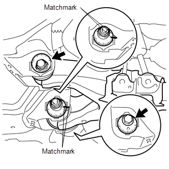 (a) Install the lower suspension arm with the camber adjusting cam, No. 2 camber adjusting cam, No. 2 toe adjusting plate, toe adjusting cam, bolt, nut and washer. (b) Align the matchmarks on the No. 2 camber adjusting cam and No. 2 toe adjusting plate. Temporarily install the bolt and nut. 2. CONNECT FRONT LOWER BALL JOINT ATTACHMENT LH 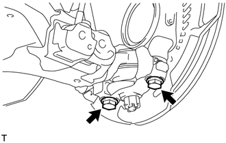 (a) Connect the attachment to the steering knuckle with the 2 bolts. Torque: 300 N·m {3059 kgf·cm, 221 ft·lbf} 3. CONNECT FRONT SHOCK ABSORBER WITH COIL SPRING LH 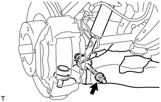 (a) Connect the shock absorber with the bolt and nut. 4. INSTALL FRONT STABILIZER LINK ASSEMBLY LH
5. STABILIZE SUSPENSION
6. TIGHTEN FRONT NO. 1 SUSPENSION ARM LOWER SUB-ASSEMBLY LH (a) Tighten the bolt and nut. Torque: 280 N·m {2855 kgf·cm, 207 ft·lbf} 7. TIGHTEN FRONT SHOCK ABSORBER WITH COIL SPRING (a) Tighten the nut. Torque: 195 N·m {1988 kgf·cm, 144 ft·lbf} 8. INSTALL FRONT WHEEL Torque: for Aluminum Wheel : 131 N·m {1336 kgf·cm, 97 ft·lbf} for Steel Wheel : 209 N·m {2131 kgf·cm, 154 ft·lbf} 9. INSPECT AND ADJUST FRONT WHEEL ALIGNMENT (a) Inspect and adjust the front wheel alignment (see page
|
Toyota Tundra Service Manual > Lighting System: Precaution
PRECAUTION PRECAUTION FOR BULB REPLACEMENT (a) Always prepare a new bulb for immediate replacement. While replacing a bulb, the lens may attract dust and moisture if removed from the vehicle for a long time. (b) Always replace a bulb with another bulb of the same wattage. (c) If only replacing the b ...

 ).
).

