INSTALLATION CAUTION / NOTICE / HINT HINT: A bolt without a torque specification is shown in the standard bolt chart (see
page PROCEDURE 1. INSTALL UPPER CAB REAR PILLAR PLATE LH 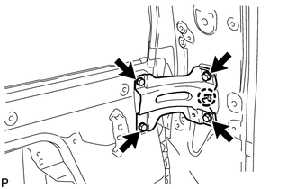
(a) Align the positioning hole with the claw, and install the upper plate with the 4 bolts as shown in the illustration. 2. INSTALL UPPER CAB REAR PILLAR PLATE RH HINT: Use the same procedures described for the LH side. 3. INSTALL BACK WINDOW OUTSIDE MOULDING 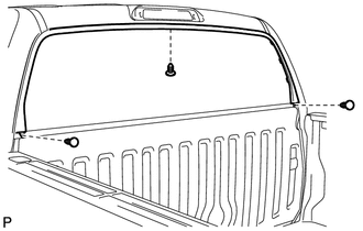
(a) Install the outside moulding with the 3 clips. (b) Using an air riveter or hand riveter with a nose piece, install the back window outside moulding with 16 new rivets. 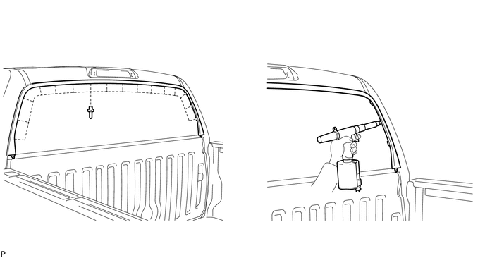
HINT: If the rivet cannot be cut, pull it once and cut it. NOTICE: 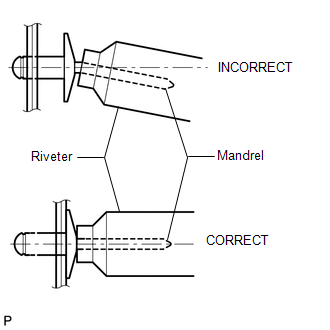
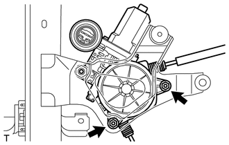
4. INSTALL BACK DOOR POWER WINDOW REGULATOR MOTOR 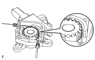
(a) Install the drum and wire guide to the motor. (b) Install the cover with the 2 screws. (c) Apply MP grease to the rotating areas of the regulator motor.
5. INSTALL BACK DOOR POWER WINDOW REGULATOR SUB-ASSEMBLY 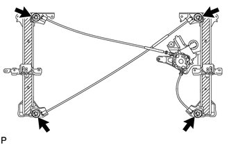
(a) Apply MP grease to the sliding and rotating parts of the window regulator. NOTICE: Do not apply grease to the spring of the window regulator. (b) Temporarily install the window regulator by attaching the 3 upper claws. 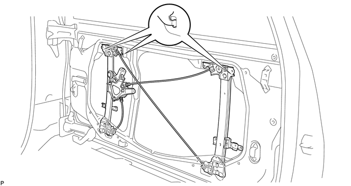
(c) Loosely install the bolts onto the window regulator. NOTICE: Be careful not to drop and deform the window regulator. (d) Tighten the 7 bolts in the order shown in the illustration. 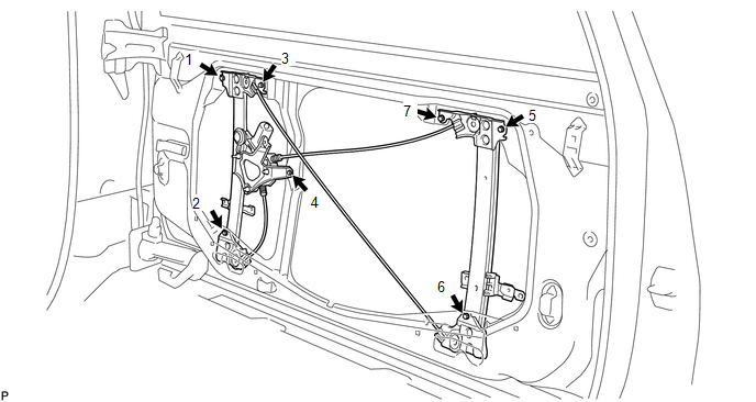
Torque: 8.0 N·m {82 kgf·cm, 71 in·lbf} 6. INSTALL BACK WINDOW GLASS (a) Temporarily install the back window glass to the window regulator with the 4 bolts. (b) Tighten the 4 bolts in the order shown in the illustration. Torque: 8.0 N·m {82 kgf·cm, 71 in·lbf} NOTICE: Do not damage the back window glass. (c) Connect the 2 defogger connectors labeled A. 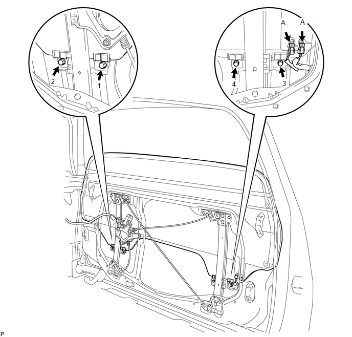
7. INSTALL BACK DOOR GLASS RUN 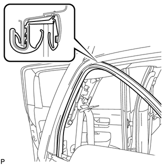
(a) Install the glass run. 8. INSTALL INNER BACK DOOR GLASS WEATHERSTRIP 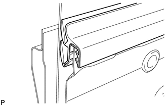
(a) Install the inner weatherstrip. 9. INSTALL OUTER BACK DOOR GLASS WEATHERSTRIP ASSEMBLY (a) Install the outer weatherstrip with the 9 clips. 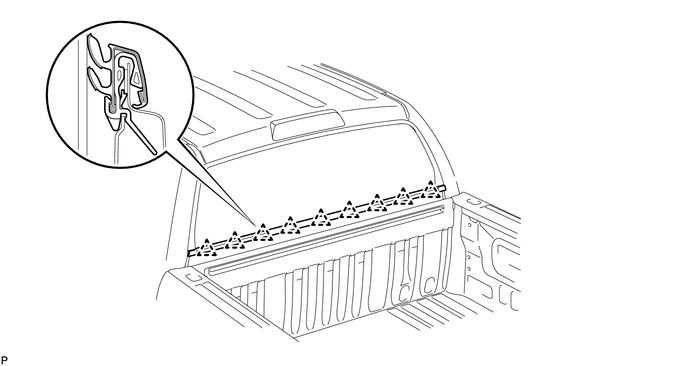
10. INSTALL BACK DOOR SERVICE HOLE COVER (a) Slide the cover to the right to engage the retainer labeled A. (b) Attach the claw labeled B to the body. (c) Install the 12 bolts and nut. (d) Install the back window regulator connector labeled C. 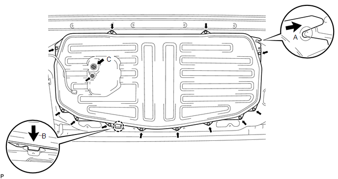
11. INSTALL ROOF HEADLINING ASSEMBLY (a) Return the roof headlining to its original position. Refer to the following
procedures (see page 12. INSTALL NO. 1 ROOM LIGHT ASSEMBLY
13. INSTALL ASSIST GRIP SUB-ASSEMBLY
14. INSTALL FRONT QUARTER TRIM PANEL ASSEMBLY LH
15. INSTALL FRONT QUARTER TRIM PANEL ASSEMBLY RH
16. INSTALL LOWER QUARTER TRIM PANEL ASSEMBLY LH
17. INSTALL LOWER QUARTER TRIM PANEL ASSEMBLY RH
18. INSTALL FRONT SHOULDER BELT ANCHOR PLATE SUB-ASSEMBLY LH
19. INSTALL FRONT SHOULDER BELT ANCHOR PLATE SUB-ASSEMBLY RH HINT: Use the same procedures described for the LH side. 20. INSTALL NO. 1 BOX SPEAKER ASSEMBLY
21. INSTALL REAR DOOR OPENING TRIM WEATHERSTRIP LH 22. INSTALL REAR DOOR OPENING TRIM WEATHERSTRIP RH 23. INSTALL REAR DOOR SCUFF PLATE LH
24. INSTALL REAR DOOR SCUFF PLATE RH
25. INSTALL REAR SEAT ASSEMBLY LH
26. INSTALL REAR SEAT ASSEMBLY RH
27. INSTALL REAR ROOF DRIP SIDE FINISH MOULDING LH
28. INSTALL REAR ROOF DRIP SIDE FINISH MOULDING RH HINT: Use the same procedures described for the LH side. 29. CONNECT CABLE TO NEGATIVE BATTERY TERMINAL |
Toyota Tundra Service Manual > Vehicle Stability Control System: Steering Angle Sensor Initialization Incomplete (C1439,C1445)
DESCRIPTION When the vehicle is being driven in a straight line at 12.8 km/h (8 mph) for 1 second or more, the skid control ECU (brake actuator assembly) calculates the steering angle sensor zero point and updates the zero point if the difference between the calculated zero point and current zero po ...

 ).
).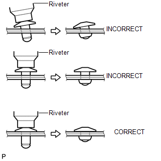 Confirm that the rivets are
seated properly against the moulding.
Confirm that the rivets are
seated properly against the moulding. 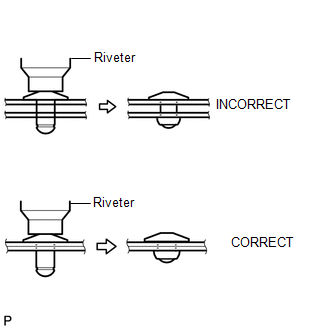 Do not leave any space between
the moulding and door frame. Firmly hold together the 2 items while installing
the rivet.
Do not leave any space between
the moulding and door frame. Firmly hold together the 2 items while installing
the rivet.