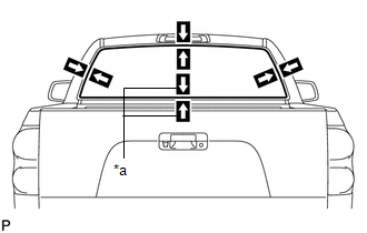
INSTALLATION PROCEDURE 1. INSTALL NO. 1 BACK WINDOW GLASS SPACER 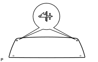
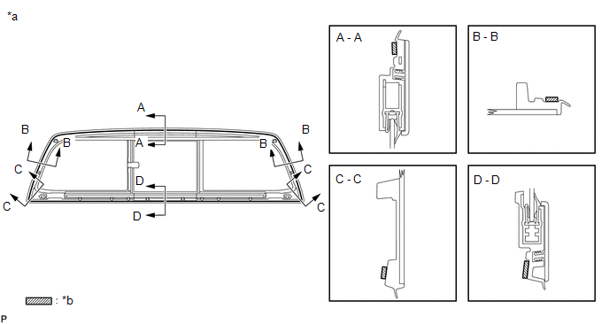
(a) Install 2 new spacers onto the back window assembly as shown in the illustration. 2. INSTALL NO. 2 BACK WINDOW GLASS SPACER 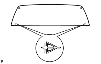
(a) Install 2 new spacers onto the back window assembly as shown in the illustration. 3. INSTALL BACK WINDOW ASSEMBLY 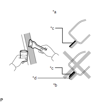
(a) Using a brush or sponge, apply body primer to the exposed part of the vehicle body. NOTICE:
(b) Using a brush or sponge, apply glass primer to the contact surface of the back window. 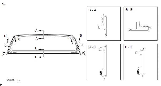
HINT: If primer is applied to an area that is not specified, wipe off the primer with a non-residue solvent before it dries. NOTICE:
(c) Apply adhesive to the back window. Adhesive: Toyota Genuine Windshield Glass Adhesive or equivalent (1) Cut off the tip of the cartridge nozzle as shown in the illustration below. HINT: After cutting off the tip, use all adhesive within the time written in the table below. Usage time frame:
(2) Load the sealer gun with the cartridge. (3) Apply adhesive to the back window as shown in the illustration. 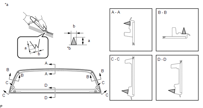
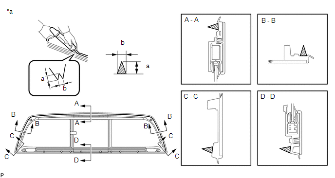
Standard:
(d) Using suction cups, position the glass so that the reference marks are aligned. Press it in gently along the rim. 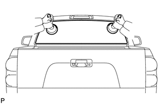
NOTICE:
(e) Lightly press the front surface of the back window to ensure that the back window is securely fit to the vehicle body. NOTICE: Check that the spacers are attached to the vehicle body correctly. (f) Using a scraper, remove any excess or protruding adhesive. NOTICE: Do not drive the vehicle within the time written in the table below. Minimum time:
4. CHECK FOR LEAK AND REPAIR (a) Conduct a leak test after the adhesive has completely hardened. (b) Seal any leaks with auto glass sealer. 5. INSTALL UPPER OUTSIDE BACK WINDOW MOULDING (for Slide Type, for Power Slide Type) 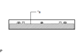
(a) Clean the back window surface. (1) Using a heat light, heat the back window surface. (2) Remove the double-sided tape from the back window. (3) Wipe off any tape adhesive residue with cleaner. (b) If reusing the moulding: Clean the moulding. (1) Using a heat light, heat the moulding. (2) Remove the double-sided tape from the moulding. (3) Wipe off any tape adhesive residue with cleaner. (4) Apply new double-sided tape to the moulding, as shown in the illustration. (c) Install the moulding. (1) Using a heat light, heat the back window and moulding. (2) Remove the peeling paper. (3) Attach the 3 clips to install the moulding. 6. INSTALL LOWER OUTSIDE BACK WINDOW MOULDING (for Slide Type, for Power Slide Type) 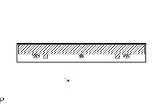
(a) Clean the back window surface. (1) Using a heat light, heat the back window surface. (2) Remove the double-sided tape from the back window. (3) Wipe off any tape adhesive residue with cleaner. (b) If reusing the moulding: Clean the moulding. (1) Using a heat light, heat the moulding. (2) Remove the double-sided tape from the moulding. (3) Wipe off any tape adhesive residue with cleaner. (4) Apply new double-sided tape to the moulding, as shown in the illustration. (c) Install the moulding. (1) Using a heat light, heat the back window and moulding. (2) Remove the peeling paper. (3) Attach the 3 clips to install the moulding. 7. INSTALL REAR ROOF DRIP SIDE FINISH MOULDING LH Click here 8. INSTALL REAR ROOF DRIP SIDE FINISH MOULDING RH HINT: Use the same procedures described for the LH side. 9. INSTALL ROOF HEADLINING ASSEMBLY Click here 10. INSTALL BACK DOOR GLASS CHANNEL (for Power Slide Type) HINT: Perform these procedures only when replacing the back window glass. (a) Using a brush or sponge, coat the application area of a new back window glass with glass primer. 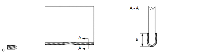
Standard:
NOTICE:
HINT: If the primer is applied to an area that is not specified, apply non-residue solvent to a clean cloth and wipe off the excess primer before it dries.
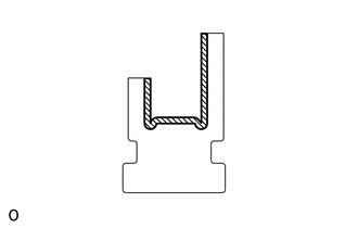
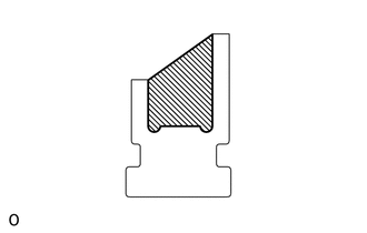
(c) Apply adhesive to the back door glass channel. Adhesive: Toyota Genuine Windshield Glass Adhesive or equivalent (1) Cut off the tip of a cartridge nozzle. HINT: After cutting off the tip, use all adhesive within the time written in the table below. Usage Time Frame:
(3) Apply adhesive to the back door glass channel as shown in the illustration. (d) Install the back door glass as shown in the illustration. 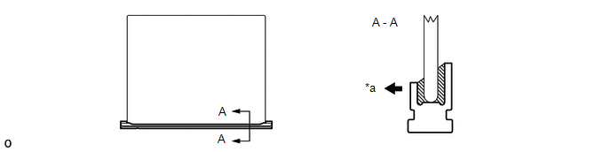
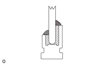
11. INSTALL BACK WINDOW GLASS WITH BACK DOOR GLASS CHANNEL (for Power Slide Type) HINT: Perform these procedures only when replacing the back window glass. (a) Insert the back window glass into the channel (arrow 1). Attach the upper part of the back window glass to the upper channel (arrow 2). Then slide the back window glass towards the RH side (arrow 3) so that the glass channel fits between the ribs to install the back window glass. (b) Insert the seal into the bottom of the channel (arrow 4), and then slightly push the seal to the channel (arrow 5) to install it. (c) Using a T10 "TORX" driver, install the stopper with the screw (illustration A). 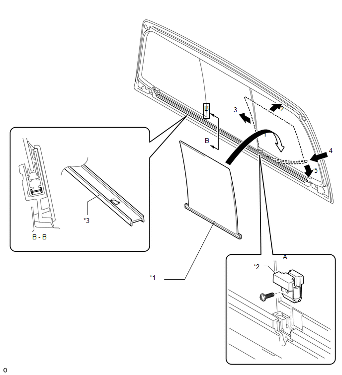
12. INSTALL POWER WINDOW REGULATOR MOTOR ASSEMBLY (for Power Slide Type) 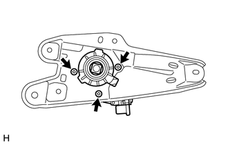
(a) Using a T25 "TORX" socket, install the power window regulator motor to the base plate with the 3 screws. Torque: 5.4 N·m {55 kgf·cm, 48 in·lbf} 13. INSTALL DOOR WINDOW REGULATOR BASE PLATE (for Power Slide Type) 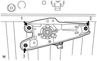
(a) Install the door window regulator base plate with the 3 nuts in the order shown in the illustration. Torque: 8.0 N·m {82 kgf·cm, 71 in·lbf} 14. INSTALL DOOR WINDOW REGULATOR CABLE SUB-ASSEMBLY (for Power Slide Type) 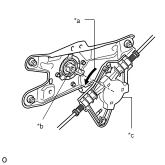
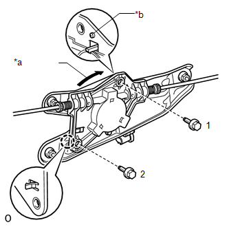
(a) Rotate the drum assembly counterclockwise to align it with the motor pivot pin, and then connect the motor drum assembly to the motor pivot pin. NOTICE: Do not rotate the drum assembly more than 45°.
(c) Install the 2 bolts in the order shown in the illustration. Torque: 5.5 N·m {56 kgf·cm, 49 in·lbf} (d) Insert the wires into the back window as shown in the illustration labeled A. 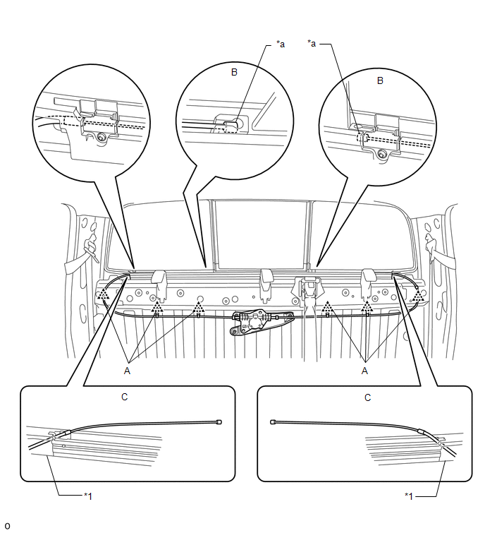
(e) Compress the springs to release the tension in the cables, connect the wire ends to the back window as shown in the illustration labeled B, Then release the springs to restore the tension. 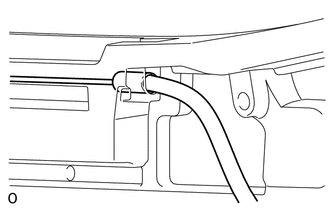
NOTICE: Insert the cables so that the caps are fully inserted into the stoppers as shown in the illustration. HINT: Use the same procedure described for the LH side. (f) Attach the 6 clips labeled C in the illustration. 15. INSTALL NO. 1 BACK PANEL SILENCER (for Power Slide Type) 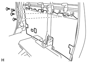
(a) Install the No. 1 back panel silencer with the 4 clips. 16. INSTALL COAT HOOK Click here 17. INSTALL NO. 1 ROOM LIGHT ASSEMBLY Click here 18. INSTALL FRONT QUARTER TRIM PANEL ASSEMBLY LH Click here 19. INSTALL FRONT QUARTER TRIM PANEL ASSEMBLY RH HINT: Use the same procedures described for the LH side. 20. INSTALL LOWER QUARTER TRIM PANEL ASSEMBLY LH Click here 21. INSTALL LOWER QUARTER TRIM PANEL ASSEMBLY RH HINT: Use the same procedures described for the LH side. 22. INSTALL REAR DOOR OPENING TRIM WEATHERSTRIP LH Click here 23. INSTALL REAR DOOR OPENING TRIM WEATHERSTRIP RH HINT: Use the same procedures described for the LH side. 24. INSTALL REAR DOOR SCUFF PLATE LH Click here 25. INSTALL REAR DOOR SCUFF PLATE RH Click here 26. INSTALL REAR SEAT ASSEMBLY Click here 27. INSTALL FRONT SEAT ASSEMBLY (for Center Seat) Click here 28. INSTALL FRONT SEAT ASSEMBLY (for Power Seat) Click here 29. INSTALL FRONT SEAT ASSEMBLY (for Manual Seat) Click here |
Toyota Tundra Service Manual > Brake System: Precaution
PRECAUTION NOTICE: Make sure to replace each part properly. Improper installation or repair could affect the performance of the brake system and cause a driving hazard. It is very important to keep the brake system parts and the work area clean when repairing the brake system. If the vehicle is equi ...