TERMINALS OF ECU
1. CHECK FRONT POWER WINDOW REGULATOR MOTOR ASSEMBLY LH

(a) Disconnect the N12 motor connector.
(b) Measure the resistance and voltage according to the value(s) in the table
below.
|
Terminal No. (Symbol)
|
Wiring Color
|
Terminal Description
|
Condition
|
Specified Condition
|
|
N12-2 (B) - Body ground
|
P - Body ground
|
Battery power supply
|
Always
|
11 to 14 V
|
|
N12-1 (GND) - Body ground
|
W-B - Body ground
|
Ground
|
Always
|
Below 1 Ω
|
(c) Reconnect the N12 motor connector.
(d) Measure the voltage according to the value(s) in the table below.
|
Terminal No. (Symbol)
|
Wiring Color
|
Terminal Description
|
Condition
|
Specified Condition
|
|
N12-10 (UP) - N12-1 (GND)
|
BE - W-B
|
Power window UP operation
|
Ignition switch ON
Master switch
OFF → UP
|
11 to 14 V → Below 1 V
|
|
N12-10 (UP) - N12-1 (GND)
|
BE - W-B
|
Power window UP operation
|
Ignition switch ON
Door glass fully open → power window AUTO UP operation → door glass fully
closed
|
11 to 14 V → Below 1 V → 11 to 14 V
|
|
N12-7 (DOWN) - N12-1 (GND)
|
BR - W-B
|
Power window DOWN operation
|
Ignition switch ON
Master switch
OFF → DOWN
|
11 to 14 V → Below 1 V
|
|
N12-7 (DOWN) - N12-1 (GND)
|
BR - W-B
|
Power window DOWN operation
|
Ignition switch ON
Door glass fully closed → power window AUTO DOWN operation → door glass
fully open
|
11 to 14 V → Below 1 V → 11 to 14 V
|
If the result is not as specified, the motor may be malfunctioning.

2. CHECK FRONT POWER WINDOW REGULATOR MOTOR RH
(a) Disconnect the M11 motor connector.
(b) Measure the resistance and voltage according to the value(s) in the table
below.
|
Terminal No. (Symbol)
|
Wiring Color
|
Terminal Description
|
Condition
|
Specified Condition
|
|
M11-2 (B) - Body ground
|
V - Body ground
|
Battery power supply
|
Always
|
11 to 14 V
|
|
M11-1 (GND) - Body ground
|
W-B - Body ground
|
Ground
|
Always
|
Below 1 Ω
|
If the result is not as specified, there may be a malfunction on the wire harness
side.
(c) Reconnect the M11 motor connector.
(d) Measure the voltage according to the value(s) in the table below.
|
Terminal No. (Symbol)
|
Wiring Color
|
Terminal Description
|
Condition
|
Specified Condition
|
|
M11-10 (UP) - M11-1 (GND)
|
G - W-B
|
Power window UP operation
|
Ignition switch ON
Power window regulator switch assembly
OFF → UP
|
11 to 14 V → Below 1 V
|
|
M11-10 (UP) - M11-1 (GND)
|
G - W-B
|
Power window UP operation
|
Ignition switch ON
Door glass fully open → power window AUTO UP operation → door glass fully
closed
|
11 to 14 V → Below 1 V → 11 to 14 V
|
|
M11-7 (DOWN) - M11-1 (GND)
|
P - W-B
|
Power window DOWN operation
|
Ignition switch ON
Power window regulator switch assembly
OFF → DOWN
|
11 to 14 V → Below 1 V
|
|
M11-7 (DOWN) - M11-1 (GND)
|
P - W-B
|
Power window DOWN operation
|
Ignition switch ON
Door glass fully closed → power window AUTO DOWN operation → door glass
fully open
|
11 to 14 V → Below 1 V → 11 to 14 V
|
|
M11-4 (AUTO) - M11-1 (GND)
|
B - W-B
|
Power window AUTO UP/DOWN operation
|
Ignition switch ON
Power window regulator switch assembly
OFF → AUTO UP/DOWN operation
|
11 to 14 V → Below 1 V
|
(e) Measure the pulse according to the value(s) in the table below.
|
Terminal No. (Symbol)
|
Wiring Color
|
Terminal Description
|
Condition
|
Specified Condition
|
|
M11-9 (LIN) - M11-1 (GND)
|
L - W-B
|
LIN communication signal
|
Ignition switch ON
|
Pulse generation
|
3. CHECK POWER WINDOW REGULATOR MASTER SWITCH

(a) Disconnect the N2 master switch connector.
(b) Measure the resistance and voltage according to the value(s) in the table
below.
|
Terminal No. (Symbol)
|
Wiring Color
|
Terminal Description
|
Condition
|
Specified Condition
|
|
N2-3 (B) - Body ground
|
R - Body ground
|
Battery power supply
|
Always
|
11 to 14 V
|
|
N2-13 (B) - Body ground
|
G - Body ground
|
Battery power supply
|
Ignition switch ON
|
11 to 14 V
|
|
N2-1 (E) - Body ground
|
W-B - Body ground
|
Ground
|
Always
|
Below 1 Ω
|
(c) Reconnect the N2 master switch connector.
(d) Measure the voltage according to the value(s) in the table below.
|
Terminal No. (Symbol)
|
Wiring Color
|
Terminal Description
|
Condition
|
Specified Condition
|
|
N2-4 (UP) - N2-1 (E)
|
BE - W-B
|
Driver side door power window UP operation
|
Ignition switch ON, driver side switch of master switch OFF → UP
|
11 to 14 V → Below 1 V
|
|
N2-4 (UP) - N2-1 (E)
|
BE - W-B
|
Driver side door power window AUTO UP operation
|
Ignition switch ON, driver side door glass fully open → power window
AUTO UP operation → driver side door glass fully closed
|
11 to 14 V → Below 1 V → 11 to 14 V
|
|
N2-5 (DOWN) - N2-1 (E)
|
BR - W-B
|
Driver side door power window DOWN operation
|
Ignition switch ON, driver side switch of master switch OFF → DOWN
|
11 to 14 V → Below 1 V
|
|
N2-5 (DOWN) - N2-1 (E)
|
BR - W-B
|
Driver side door power window AUTO DOWN operation
|
Ignition switch ON, driver side door glass fully closed → power window
AUTO DOWN operation → driver side door glass fully open
|
11 to 14 V → Below 1 V → 11 to 14 V
|
|
N2-12 (U) - N2-1 (E)
|
V - W-B
|
Rear LH side door power window UP operation
|
Ignition switch ON, rear LH switch of master switch OFF → UP
|
Below 1 V → 11 to 14 V
|
|
N2-15 (D) - N2-1 (E)
|
B - W-B
|
Rear LH side door power window DOWN operation
|
Ignition switch ON, rear LH switch of master switch OFF → DOWN
|
Below 1 V → 11 to 14 V
|
|
N2-10 (U) - N2-1 (E)
|
BE - W-B
|
Rear RH side door power window UP operation
|
Ignition switch ON, rear RH switch of master switch OFF → UP
|
Below 1 V → 11 to 14 V
|
|
N2-16 (D) - N2-1 (E)
|
LG - W-B
|
Rear RH side door power window DOWN operation
|
Ignition switch ON, rear RH switch of master switch OFF → DOWN
|
Below 1 V → 11 to 14 V
|
|
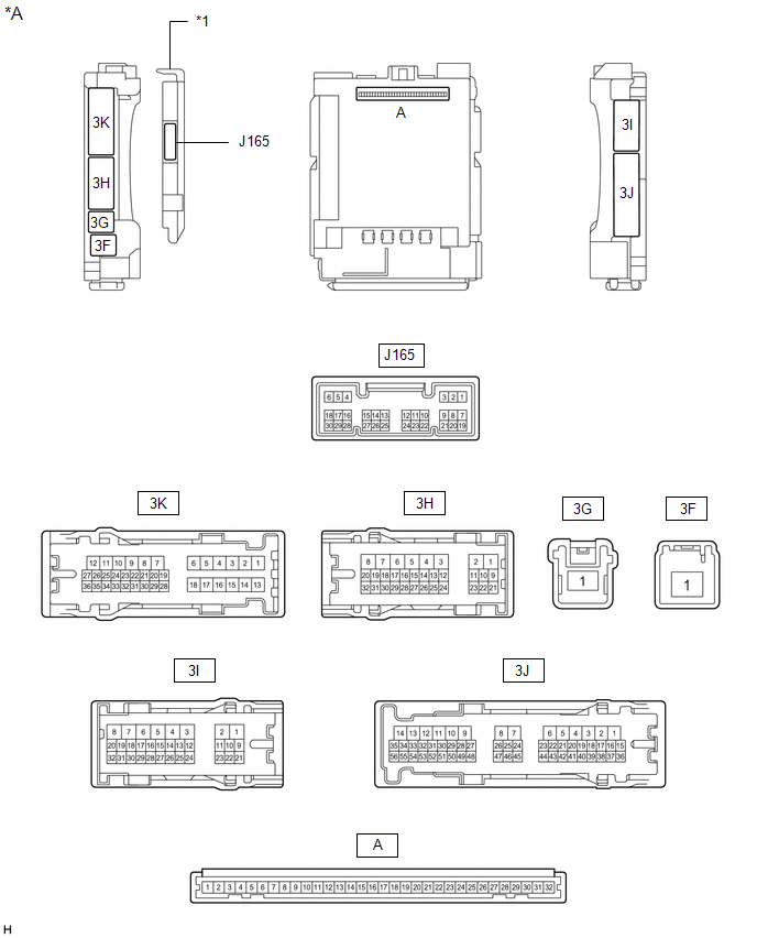
*A
|
Main Body ECU (Multiplex Network Body ECU) with 1 connector
|
-
|
-
|
|
*1
|
Main Body ECU (Multiplex Network Body ECU)
|
-
|
-
|
|
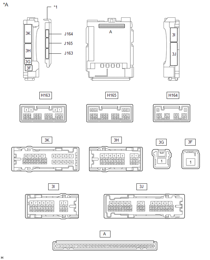
*A
|
Main Body ECU (Multiplex Network Body ECU) with 3 connectors
|
-
|
-
|
|
*1
|
Main Body ECU (Multiplex Network Body ECU)
|
-
|
-
|
4. CHECK DRIVER SIDE JUNCTION BLOCK ASSEMBLY AND MAIN BODY ECU (MULTIPLEX NETWORK
BODY ECU)
(a) Remove the main body ECU (multiplex network body ECU) from the cowl side
junction block LH.
Click here 
(b) Measure the voltage and resistance according to the value(s) in the table
below.
|
Terminal No. (Symbol)
|
Wiring Color
|
Terminal Description
|
Condition
|
Specified Condition
|
|
A-30 (ACC) - Body ground
|
None - Body ground
|
ACC power supply
|
Ignition switch ON
|
11 to 14 V
|
|
Ignition switch off
|
Below 1 V
|
|
A-32 (IG) - Body ground
|
None - Body ground
|
IG power supply
|
Ignition switch ON
|
11 to 14 V
|
|
Ignition switch off
|
Below 1 V
|
|
A-11 (GND1) - Body ground
|
None - Body ground
|
Body ground
|
Always
|
Below 1 Ω
|
|
J165-6 (FLCY) - Body ground
|
GR - Body ground
|
Front door courtesy light switch LH signal
|
Front door LH open
|
Below 1 Ω
|
|
Front door LH closed
|
10 kΩ or higher
|
|
J165-27 (FRCY) - Body ground
|
W - Body ground
|
Front door courtesy light switch RH signal
|
Front door RH open
|
Below 1 Ω
|
|
Front door RH closed
|
10 kΩ or higher
|
| 

