SYSTEM DIAGRAM 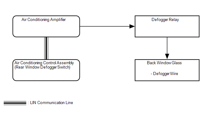 Communication Table Communication Table
|
Toyota Tundra Service Manual > Rear Combination Light Assembly: Installation
INSTALLATION CAUTION / NOTICE / HINT HINT: Use the same procedure for the RH and LH sides. The procedure listed below is for the LH side. A bolt without a torque specification is shown in the standard bolt chart (See page ). PROCEDURE 1. INSTALL REAR COMBINATION LIGHT GUIDE HINT: If the rear combina ...


