Toyota Tundra Service Manual: Terminals Of Ecu

TERMINALS OF ECU

1. CHECK AIR CONDITIONING AMPLIFIER

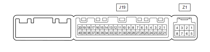
(a) Disconnect the J19 air conditioning amplifier connector.

(b) Measure the resistance and voltage according to the value(s) in the table below.

Terminal No. (Symbol)

Wiring Color

Terminal Description

Condition

Specified Condition

J19-1 (IG+) - J19-14 (GND)

B - W-B

Ignition power supply

Ignition switch ON

11 to 14 V

Ignition switch OFF

Below 1 V

J19-21 (B) - J19-14 (GND)

GR - W-B

Battery power source

Always

11 to 14 V

J19-14 (GND) - Body ground

W-B - Body ground

Ground

Always

Below 1 Ω

J19-37 (LIN1) - J19-14 (GND)

SB - W-B

LIN communication signal

Ignition switch ON

Pulse generation

(c) Reconnect the J19 air conditioning amplifier connector.

(d) Measure the voltage according to the value(s) in the table below.

Terminal No. (Symbol)

Wiring Color

Terminal Description

Condition

Specified Condition

J19-38 (RDEF) - J19-14 (GND)

Y - W-B

Defogger relay

Ignition switch ON, rear window defogger switch off

11 to 14 V

Ignition switch ON, rear window defogger switch on

Below 1 V

2. CHECK AIR CONDITIONING CONTROL ASSEMBLY

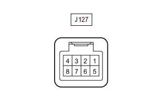
(a) Disconnect the J127 air conditioning control assembly connector.

(b) Measure the voltage and resistance according to the value(s) in the table below.

Terminal No. (Symbol)

Wiring Color

Terminal Description

Condition

Specified Condition

J127-4 (IG+) - J127-5 (GND)

Y - W-B

Ignition power supply

Ignition switch ON

11 to 14 V

Ignition switch OFF

Below 1 V

J127-5 (GND) - Body ground

W-B - Body ground

Ground

Always

Below 1 Ω

J127-7 (STX) - J127-5 (GND)

SB - W-B

LIN communication signal

Ignition switch ON

Pulse generation

    System Diagram

    Window Defogger Wire(for Crewmax)

    See More:

    Toyota Tundra Service Manual > Navigation System: Microphone Circuit between Microphone and Navigation Receiver Assembly
    DESCRIPTION This circuit sends a microphone signal from the telephone microphone assembly to the navigation receiver assembly. It also supplies power from the navigation receiver assembly to the telephone microphone assembly. WIRING DIAGRAM PROCEDURE 1. CHECK HARNESS AND CONNECTOR (NAVIGATION RECEIV ...

    Toyota Tundra Owners Manual

    Toyota Tundra Service Manual

    © 2025 Copyright www.ttundra.com
    0.0194