DESCRIPTION When the air conditioning control assembly (windshield deicer switch) turns is turned on, a windshield deicer activation request signal is sent via the LIN communication line to the air conditioning amplifier. Then the air conditioning amplifier operates the windshield deicer. WIRING DIAGRAM 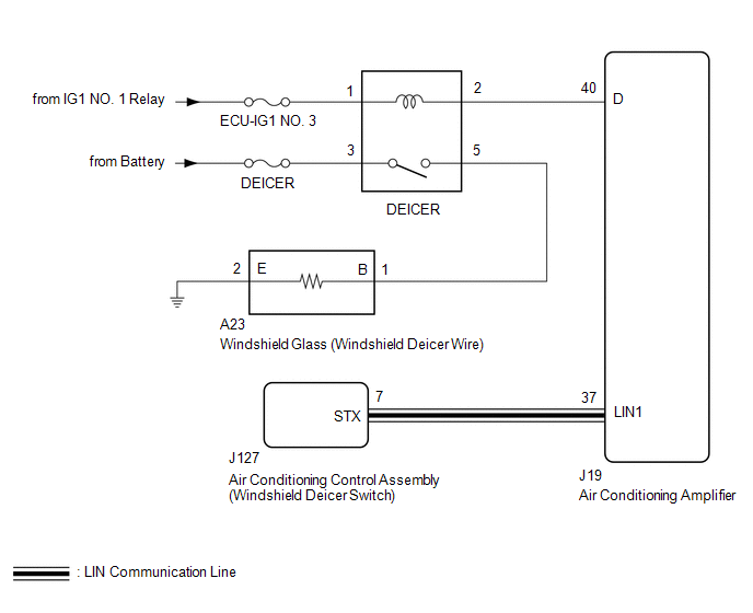
CAUTION / NOTICE / HINT HINT: This circuit uses the LIN communication line. Before performing the inspection,
check that the LIN communication system is functioning normally (see page
NOTICE: Inspect the fuses for circuits related to this system before performing the following procedure. PROCEDURE
(a) Select the Active Test using the Techstream to generate a control command,
and then check that the windshield deicer operates (See page
OK: Windshield deicer relay assembly turns ON and OFF.
(a) Temporarily replace the air conditioning control assembly with a new or normally
functioning one (See page (b) Check that the malfunction disappears. OK: Malfunction disappears.
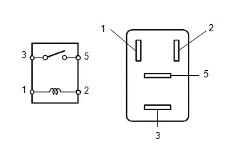
(a) Remove the windshield deicer relay assembly (DEICER) from the engine room relay block, junction block. (b) Measure the resistance according to the value(s) in the table below. Standard Resistance:
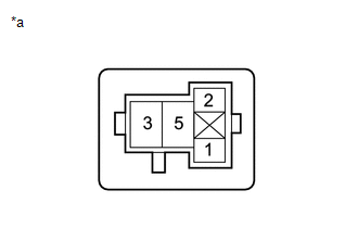
(a) Remove the windshield deicer relay assembly (DEICER) from the engine room relay block, junction block. (b) Disconnect the J19 air conditioning amplifier connector. (c) Measure the voltage according to the value(s) in the table below. Standard Voltage:
(d) Measure the resistance according to the value(s) in the table below. Standard Resistance:
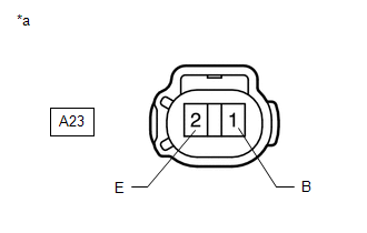
(a) Remove the windshield deicer relay assembly (DEICER) from the engine room relay block, junction block. (b) Disconnect the A23 windshield glass (windshield deicer wire) connector. (c) Measure the resistance according to the value(s) in the table below. Standard Resistance:
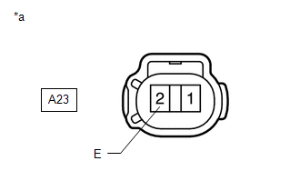
(a) Disconnect the windshield glass (windshield deicer wire) connector. (b) Measure the resistance according to the value(s) in the table below. Standard Resistance:
(a) Disconnect the windshield glass (windshield deicer wire) connector. (b) Measure the voltage according to the value(s) in the table below. Standard Voltage:
|
Toyota Tundra Service Manual > Tire And Wheel System: Inspection
INSPECTION PROCEDURE 1. INSPECT TIRE (a) Check the tires for wear and proper inflation pressure. Standard cold tire inflation pressure: Tire size Front kPa (kgf/cm2, psi) Rear kPa (kgf/cm2, psi) P255/70R18 210 (2.1, 30) 230 (2.3, 33) P275/65R18 P275/55R20 P255/70R18 (Spare Tire) P275/65R18 (Spare Ti ...

 ).
).


