Toyota Tundra Service Manual: Terminals Of Ecu

TERMINALS OF ECU

1. CHECK AIR CONDITIONING AMPLIFIER

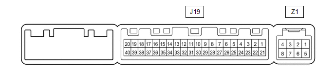
(a) Disconnect the J19 air conditioning amplifier connector.

(b) Measure the resistance and voltage according to the value(s) in the table below.

Terminal No. (Symbol)

Wiring Color

Terminal Description

Condition

Specified Condition

J19-1 (IG+) - J19-14 (GND)

B - W-B

Ignition power supply

Ignition switch ON

11 to 14 V

Ignition switch OFF

Below 1 V

J19-21 (B) - J19-14 (GND)

GR - W-B

Battery power source

Always

11 to 14 V

J19-37 (LIN1) - J19-14 (GND)

SB - W-B

LIN communication signal

Ignition switch ON

Pulse generation

J19-14 (GND) - Body ground

W-B - Body ground

Ground

Always

Below 1 Ω

(c) Reconnect the J19 air conditioning amplifier connector.

(d) Measure the voltage according to the value(s) in the table below.

Terminal No. (Symbol)

Wiring Color

Terminal Description

Condition

Specified Condition

J19-40 (D) - J19-14 (GND)

LG - W-B

Deicer relay

Ignition switch ON, windshield deicer switch off

11 to 14 V

Ignition switch ON, windshield deicer switch on

Below 1 V

2. CHECK AIR CONDITIONING CONTROL ASSEMBLY

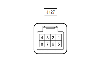
(a) Disconnect the J127 air conditioning control assembly connector.

(b) Measure the voltage and resistance according to the value(s) in the table below.

Terminal No. (Symbol)

Wiring Color

Terminal Description

Condition

Specified Condition

J127-4 (IG+) - J127-5 (GND)

Y - W-B

Ignition power supply

Ignition switch ON

11 to 14 V

Ignition switch OFF

Below 1 V

J127-5 (GND) - Body ground

W-B - Body ground

Ground

Always

Below 1 Ω

J127-7 (STX) - J127-5 (GND)

SB - W-B

LIN communication signal

Ignition switch ON

Pulse generation

    System Diagram

    Windshield Deicer does not Operate

    See More:

    Toyota Tundra Service Manual > Sfi System: Internal Control Module Throttle Position Performance (P060E)
    DESCRIPTION The ECM monitors the input signals of the Throttle Position (TP) sensor No. 1 and stop light switch. As the ECM monitors the input signals of the TP sensor No. 1 and the STP signals of the stop light switch, if the input signals and control signals deviate, a DTC is output. DTC No. DTC D ...

    Toyota Tundra Owners Manual

    Toyota Tundra Service Manual

    © 2026 Copyright www.ttundra.com
    0.0105